MITSUBISHI MICROCOMPUTERS
3822 Group
SINGLE-CHIP 8-BIT CMOS MICROCOMPUTER
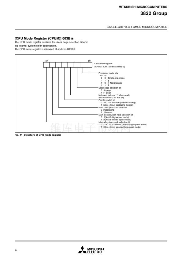
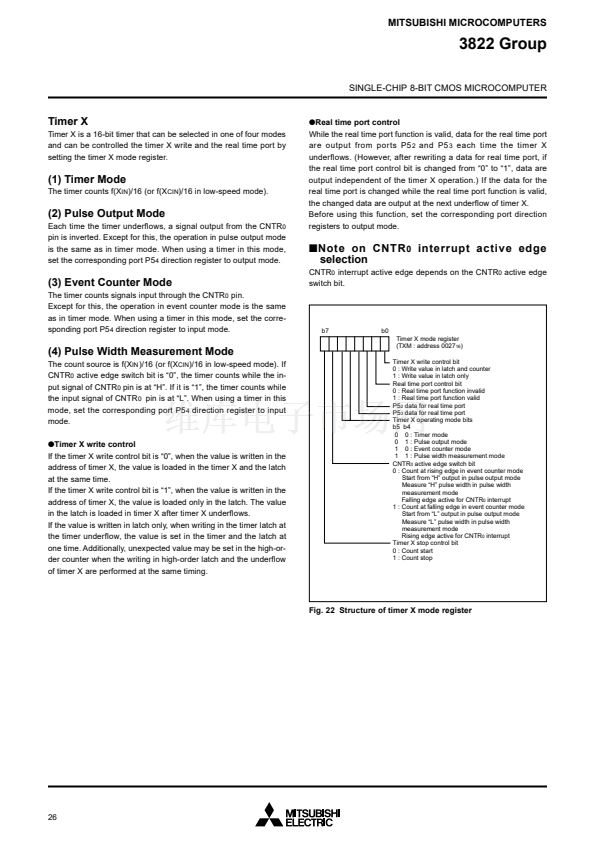
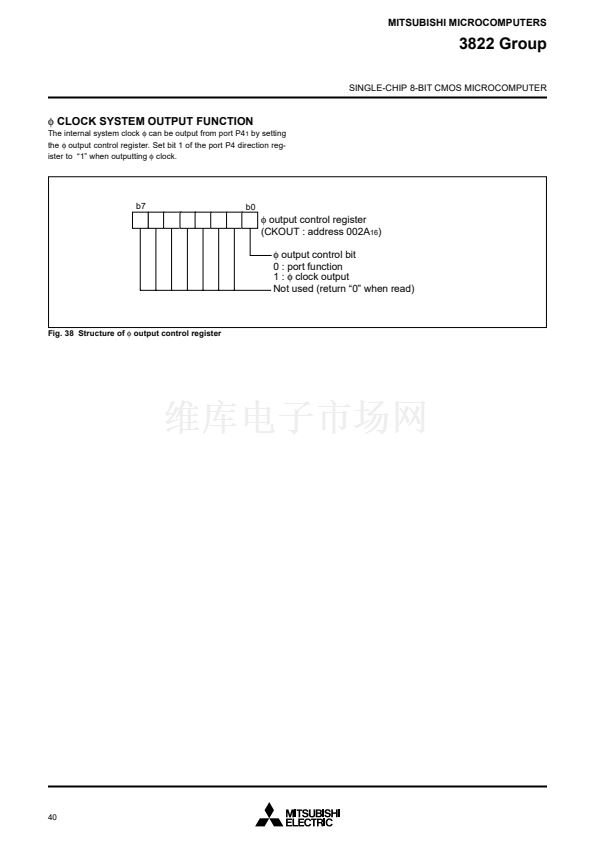
I/O PORTS
Direction Registers (ports P2, P4
1
-P4
7
, and
P5-P7)
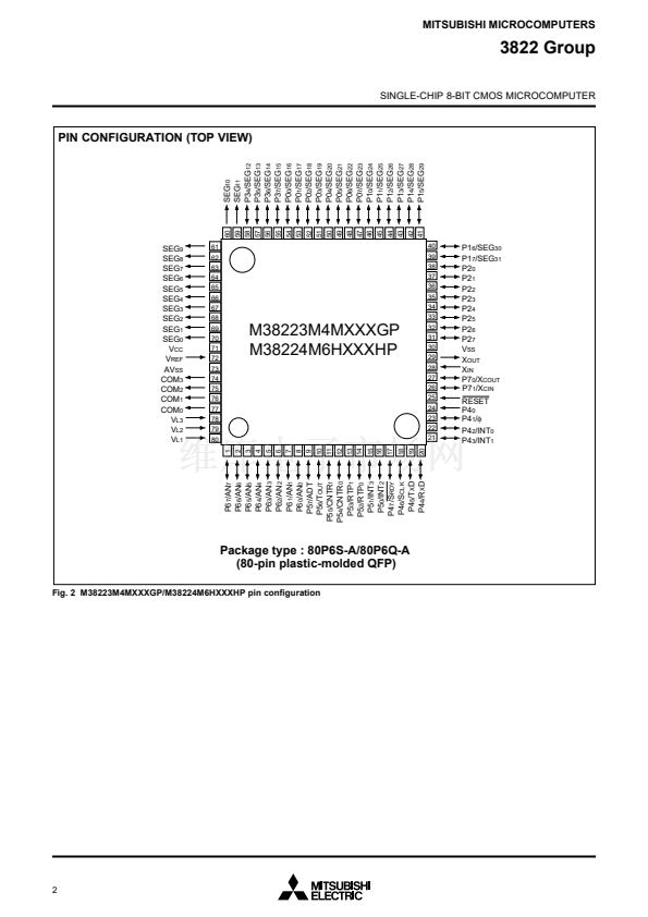
The 3822 group has 49 programmable I/O pins arranged in seven
I/O ports (ports P0鈥揚2, P4
1
鈥揚4
7
and P5-P7). The I/O ports P2,
P4
1
鈥揚4
7
and P5-P7 have direction registers which determine the
input/output direction of each individual pin. Each bit in a direction
register corresponds to one pin, and each pin can be set to be in-
put port or output port.
When 鈥?鈥?is written to the bit corresponding to a pin, that pin be-
comes an input pin. When 鈥?鈥?is written to that bit, that pin be-
comes an output pin.
If data is read from a pin set to output, the value of the port output
latch is read, not the value of the pin itself. Pins set to input are
floating. If a pin set to input is written to, only the port output latch
is written to and the pin remains floating.
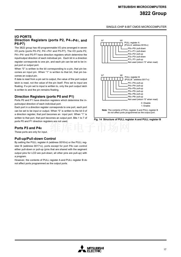
b7
b0
PULL register A
(PULLA: address 0016
16
)
P0
0
鈥揚0
7
pull-down
P1
0
鈥揚1
7
pull-down
P2
0
鈥揚2
7
pull-up
P3
4
鈥揚3
7
pull-down
P7
0
, P7
1
pull-up
Not used (return 鈥?鈥?when read)
b7
b0
PULL register B
(PULLB : address 0017
16
)
P4
1
鈥揚4
3
pull-up
P4
4
鈥揚4
7
pull-up
P5
0
鈥揚5
3
pull-up
P5
4
鈥揚5
7
pull-up
P6
0
鈥揚6
3
pull-up
P6
4
鈥揚6
7
pull-up
Not used (return 鈥?鈥?when read)
0: Disable
1: Enable
Direction Registers (ports P0 and P1)
Ports P0 and P1 have direction registers which determine the in-
put/output direction of each individual port.
Each port in a direction register corresponds to one port, each port
can be set to be input or output. When 鈥?鈥?is written to the bit 0 of
a direction register, that port becomes an input port. When 鈥?鈥?is
written to that port, that port becomes an output port. Bits 1 to 7 of
ports P0 and P1 direction registers are not used.
Note:
The contents of PULL register A and PULL register B
do not affect ports programmed as the output port.
Fig. 14 Structure of PULL register A and PULL register B
Ports P3 and P4
0
These ports are only for input.
Pull-up/Pull-down Control
By setting the PULL register A (address 0016
16
) or the PULL reg-
ister B (address 0017
16
), ports except for port P4
0
can control
either pull-down or pull-up (pins that are shared with the segment
output pins for LCD are pull-down; all other pins are pull-up) with
a program.
However, the contents of PULL register A and PULL register B do
not affect ports programmed as the output ports.
17


 1
1
 2
2
 3
3
 4
4
 5
5
 6
6
 7
7
 8
8
 9
9
 10
10
 11
11
 12
12
 13
13
 14
14
 15
15
 16
16
 17
17
 18
18
 19
19
 20
20
 21
21
 22
22
 23
23
 24
24
 25
25
 26
26
 27
27
 28
28
 29
29
 30
30
 31
31
 32
32
 33
33
 34
34
 35
35
 36
36
 37
37
 38
38
 39
39
 40
40
 41
41
 42
42
 43
43
 44
44
 45
45
 46
46
 47
47
 48
48
 49
49
 50
50
 51
51
 52
52
 53
53
 54
54
 55
55
 56
56
 57
57
 58
58
 59
59
 60
60
 61
61
 62
62
 63
63
 64
64
 65
65
 66
66
 67
67
 68
68
 69
69
 70
70
 71
71
 72
72
 73
73
 74
74
 75
75
 76
76
 77
77
 78
78
