MITSUBISHI MICROCOMPUTERS
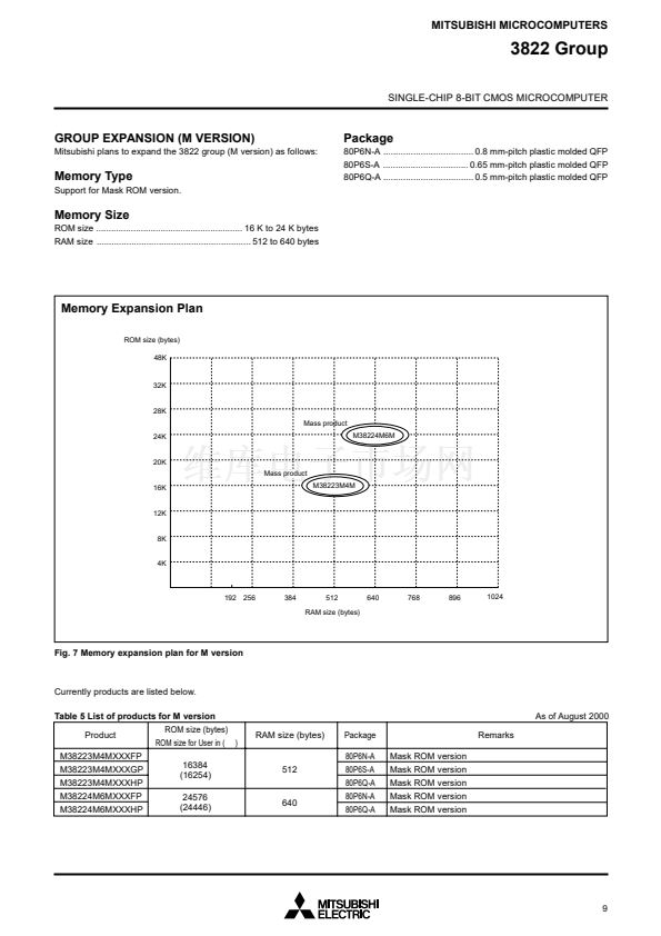
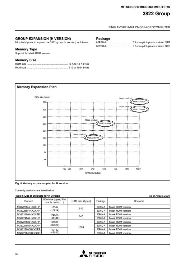
3822 Group
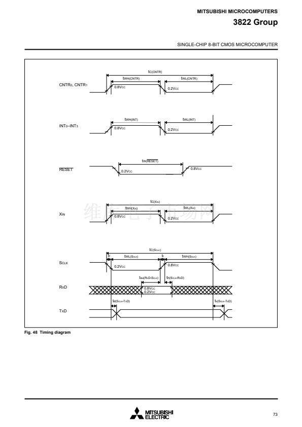
SINGLE-CHIP 8-BIT CMOS MICROCOMPUTER
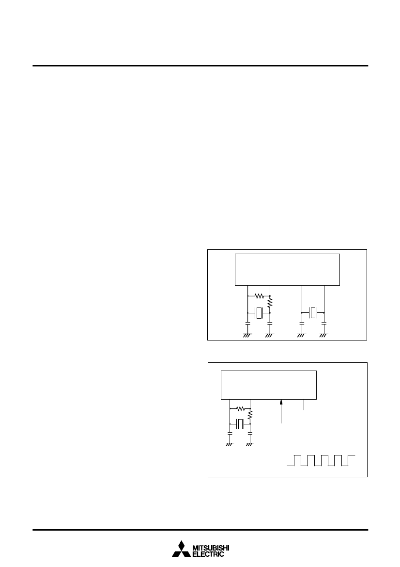
CLOCK GENERATING CIRCUIT
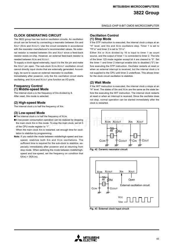
The 3822 group has two built-in oscillation circuits. An oscillation
circuit can be formed by connecting a resonator between X
IN
and
X
OUT
(X
CIN
and X
COUT
). Use the circuit constants in accordance
with the resonator manufacturer's recommended values. No exter-
nal resistor is needed between X
IN
and X
OUT
since a feed-back
resistor exists on-chip. However, an external feed-back resistor is
needed between X
CIN
and X
COUT
.
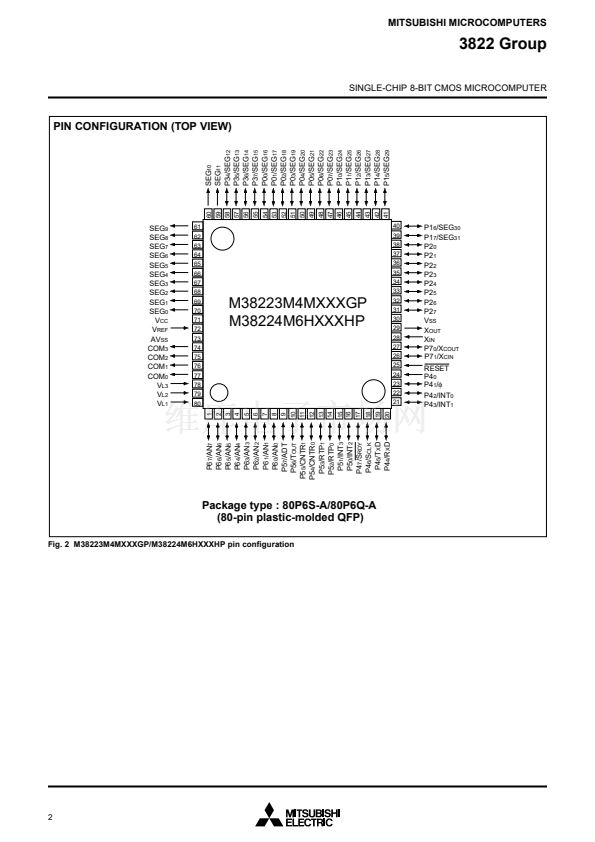
To supply a clock signal externally, input it to the X
IN
pin and make
the X
OUT
pin open. The sub-clock X
CIN
-X
COUT
oscillation circuit
cannot directly input clocks that are externally generated. Accord-
ingly, be sure to cause an external resonator to oscillate.
Immediately after poweron, only the X
IN
oscillation circuit starts
oscillating, and X
CIN
and X
COUT
pins function as I/O ports.
Oscillation Control
(1) Stop Mode
If the STP instruction is executed, the internal clock
蠁
stops at an
鈥淗鈥?level, and X
IN
and X
CIN
oscillators stop. Timer 1 is set to
鈥淔F
16
鈥?and timer 2 is set to 鈥?1
16
鈥?
Either X
IN
or X
CIN
divided by 16 is input to timer 1 as count
source, and the output of timer 1 is connected to timer 2. The bits
of the timer 123 mode register except bit 4 are cleared to 鈥?鈥? Set
the timer 1 and timer 2 interrupt enable bits to disabled (鈥?鈥? be-
fore executing the STP instruction. Oscillator restarts at reset or
when an external interrupt is received, but the internal clock
蠁
is
not supplied to the CPU until timer 2 underflows. This allows timer
for the clock circuit oscillation to stabilize.
(2) Wait Mode
Frequency Control
(1) Middle-speed Mode
The internal clock
蠁
is the frequency of X
IN
divided by 8.
After reset, this mode is selected.
If the WIT instruction is executed, the internal clock
蠁
stops at an
鈥淗鈥?level. The states of X
IN
and X
CIN
are the same as the state be-
fore the executing the WIT instruction. The internal clock restarts
at reset or when an interrupt is received. Since the oscillator does
not stop, normal operation can be started immediately after the
clock is restarted.
(2) High-speed Mode
The internal clock
蠁
is half the frequency of X
IN
.
(3) Low-speed Mode
qThe
internal clock
蠁
is half the frequency of X
CIN
.
qA
low-power consumption operation can be realized by stopping
the main clock X
IN
in this mode. To stop the main clock, set bit 5
of the CPU mode register to 鈥?鈥?
When the main clock X
IN
is restarted, set enough time for oscil-
lation to stabilize by programming.
Note:
If you switch the mode between middle/high-speed and low-
speed, stabilize both X
IN
and X
CIN
oscillations. The
sufficient time is required for the sub-clock to stabilize, es-
pecially immediately after poweron and at returning from
stop mode. When switching the mode between middle/high-
speed and low-speed, set the frequency on condition that
f(X
IN
) > 3f(X
CIN
).
X
CIN
X
COUT
Rf
C
CIN
Rd
C
COUT
X
I N
X
OUT
C
I N
C
OUT
Fig. 42 Ceramic resonator circuit
X
CIN
X
COUT
Rf
C
CIN
Rd
C
COUT
X
IN
X
OUT
Open
External oscillation circuit
V
CC
V
SS
Fig. 43 External clock input circuit
43


 1
1
 2
2
 3
3
 4
4
 5
5
 6
6
 7
7
 8
8
 9
9
 10
10
 11
11
 12
12
 13
13
 14
14
 15
15
 16
16
 17
17
 18
18
 19
19
 20
20
 21
21
 22
22
 23
23
 24
24
 25
25
 26
26
 27
27
 28
28
 29
29
 30
30
 31
31
 32
32
 33
33
 34
34
 35
35
 36
36
 37
37
 38
38
 39
39
 40
40
 41
41
 42
42
 43
43
 44
44
 45
45
 46
46
 47
47
 48
48
 49
49
 50
50
 51
51
 52
52
 53
53
 54
54
 55
55
 56
56
 57
57
 58
58
 59
59
 60
60
 61
61
 62
62
 63
63
 64
64
 65
65
 66
66
 67
67
 68
68
 69
69
 70
70
 71
71
 72
72
 73
73
 74
74
 75
75
 76
76
 77
77
 78
78
