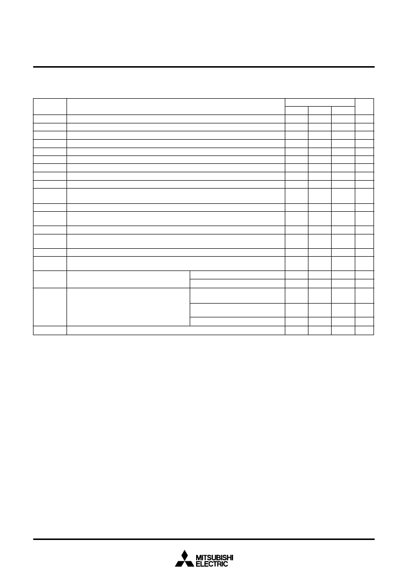
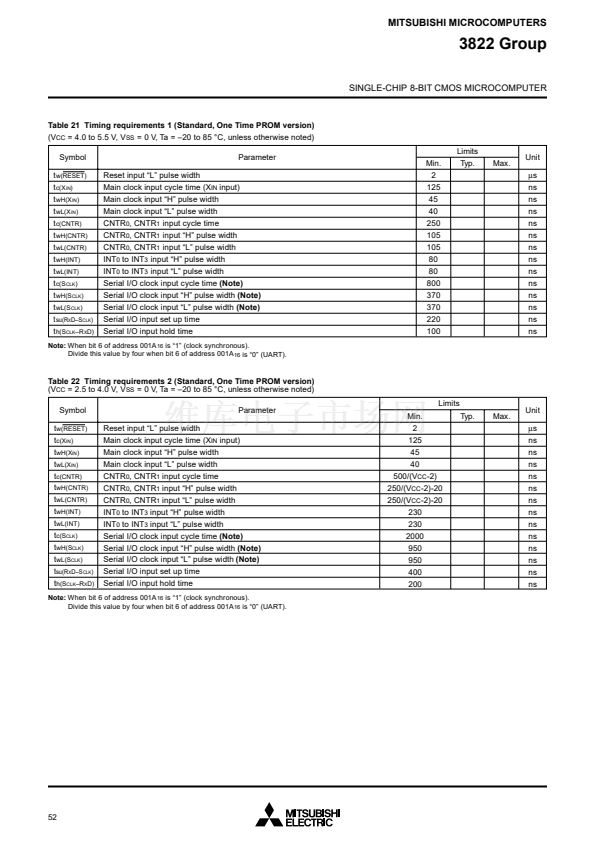
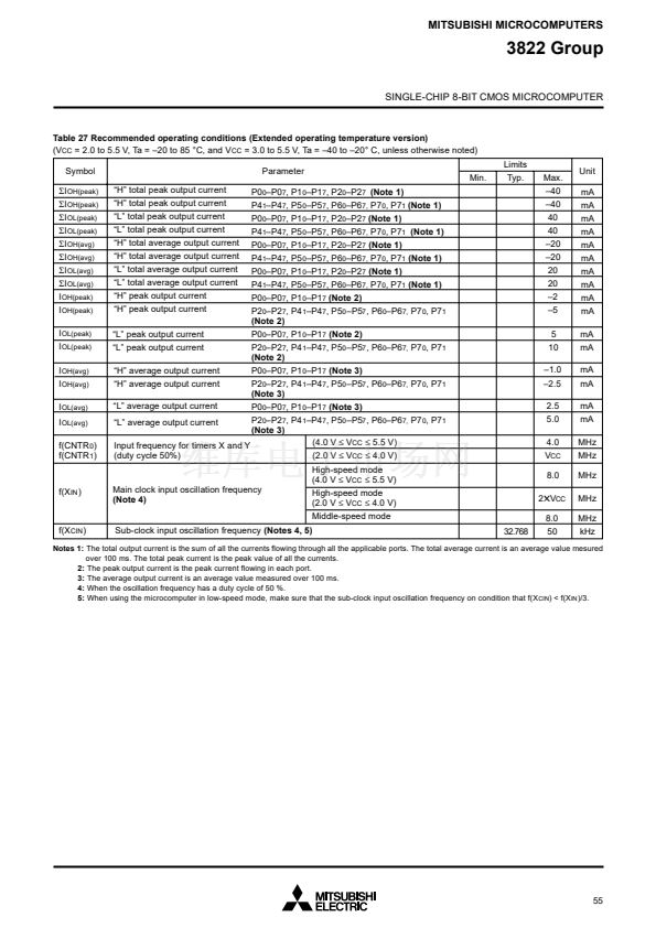
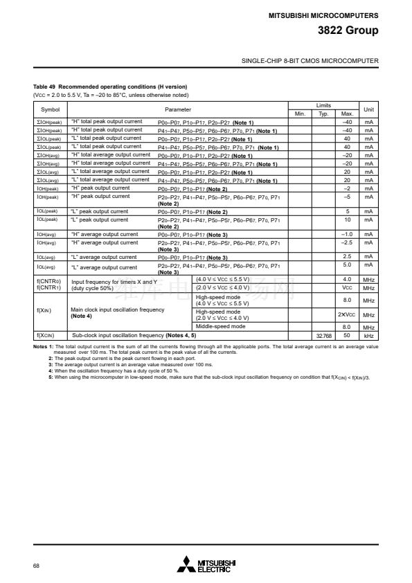
Table 27 Recommended operating conditions (Extended operating temperature version)
(V
CC
= 2.0 to 5.5 V, Ta = 鈥?0 to 85 掳C, and V
CC
= 3.0 to 5.5 V, Ta = 鈥?0 to 鈥?0掳 C, unless otherwise noted)
Symbol
危I
OH(peak)
危I
OH(peak)
危I
OL(peak)
危I
OL(peak)
危I
OH(avg)
危I
OH(avg)
危I
OL(avg)
危I
OL(avg)
I
OH(peak)
I
OH(peak)
I
OL(peak)
I
OL(peak)
I
OH(avg)
I
OH(avg)
I
OL(avg)
I
OL(avg)
f(CNTR
0
)
f(CNTR
1
)
鈥淗鈥?total peak output current
鈥淗鈥?total peak output current
鈥淟鈥?total peak output current
鈥淟鈥?total peak output current
鈥淗鈥?total average output current
鈥淗鈥?total average output current
鈥淟鈥?total average output current
鈥淟鈥?total average output current
鈥淗鈥?peak output current
鈥淗鈥?peak output current
鈥淟鈥?peak output current
鈥淟鈥?peak output current
鈥淗鈥?average output current
鈥淗鈥?average output current
鈥淟鈥?average output current
Parameter
P0
0
鈥揚0
7
, P1
0
鈥揚1
7
, P2
0
鈥揚2
7
(Note 1)
P4
1
鈥揚4
7
, P5
0
鈥揚5
7
, P6
0
鈥揚6
7,
P7
0
, P7
1
(Note 1)
P0
0
鈥揚0
7
, P1
0
鈥揚1
7
, P2
0
鈥揚2
7
(Note 1)
P4
1
鈥揚4
7
, P5
0
鈥揚5
7
, P6
0
鈥揚6
7,
P7
0
, P7
1
(Note 1)
P0
0
鈥揚0
7
, P1
0
鈥揚1
7
, P2
0
鈥揚2
7
(Note 1)
P4
1
鈥揚4
7
, P5
0
鈥揚5
7
, P6
0
鈥揚6
7,
P7
0
, P7
1
(Note 1)
P0
0
鈥揚0
7
, P1
0
鈥揚1
7
, P2
0
鈥揚2
7
(Note 1)
P4
1
鈥揚4
7
, P5
0
鈥揚5
7
, P6
0
鈥揚6
7,
P7
0
, P7
1
(Note 1)
P0
0
鈥揚0
7
, P1
0
鈥揚1
7
(Note 2)
P2
0
鈥揚2
7
, P4
1
鈥揚4
7
, P5
0
鈥揚5
7
, P6
0
鈥揚6
7,
P7
0
, P7
1
(Note 2)
P0
0
鈥揚0
7
, P1
0
鈥揚1
7
(Note 2)
P2
0
鈥揚2
7
, P4
1
鈥揚4
7
, P5
0
鈥揚5
7
, P6
0
鈥揚6
7,
P7
0
, P7
1
(Note 2)
P0
0
鈥揚0
7
, P1
0
鈥揚1
7
(Note 3)
P2
0
鈥揚2
7
, P4
1
鈥揚4
7
, P5
0
鈥揚5
7
, P6
0
鈥揚6
7,
P7
0
, P7
1
(Note 3)
Min.
Limits
Typ.
Max.
鈥?0
鈥?0
40
40
鈥?0
鈥?0
20
20
鈥?
鈥?
5
10
鈥?.0
鈥?.5
2.5
5.0
4.0
V
CC
8.0
2鉁昖
CC
8.0
50
Unit
mA
mA
mA
mA
mA
mA
mA
mA
mA
mA
mA
mA
mA
mA
mA
mA
MHz
MHz
MHz
MHz
MHz
kHz
P0
0
鈥揚0
7
, P1
0
鈥揚1
7
(Note 3)
P2
0
鈥揚2
7
, P4
1
鈥揚4
7
, P5
0
鈥揚5
7
, P6
0
鈥揚6
7,
P7
0
, P7
1
鈥淟鈥?average output current
(Note 3)
(4.0 V
鈮?/div>
V
CC
鈮?/div>
5.5 V)
Input frequency for timers X and Y
(2.0 V
鈮?/div>
V
CC
鈮?/div>
4.0 V)
(duty cycle 50%)
High-speed mode
(4.0 V
鈮?/div>
V
CC
鈮?/div>
5.5 V)
High-speed mode
(2.0 V
鈮?/div>
V
CC
鈮?/div>
4.0 V)
Middle-speed mode
32.768
f(X
IN
)
Main clock input oscillation frequency
(Note 4)
f(X
CIN
)
Sub-clock input oscillation frequency
(Notes 4, 5)
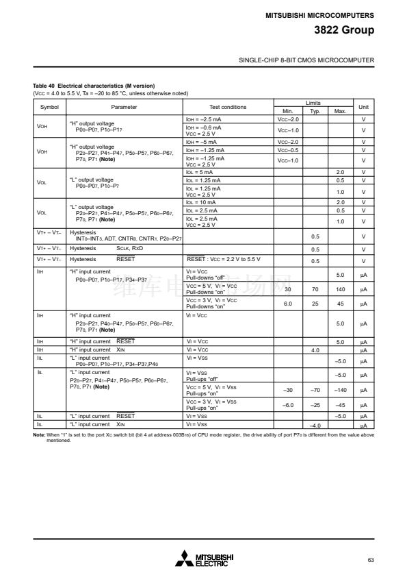
Notes 1:
The total output current is the sum of all the currents flowing through all the applicable ports. The total average current is an average value mesured
over 100 ms. The total peak current is the peak value of all the currents.
2:
The peak output current is the peak current flowing in each port.
3:
The average output current is an average value measured over 100 ms.
4:
When the oscillation frequency has a duty cycle of 50 %.
5:
When using the microcomputer in low-speed mode, make sure that the sub-clock input oscillation frequency on condition that f(X


 1
1
 2
2
 3
3
 4
4
 5
5
 6
6
 7
7
 8
8
 9
9
 10
10
 11
11
 12
12
 13
13
 14
14
 15
15
 16
16
 17
17
 18
18
 19
19
 20
20
 21
21
 22
22
 23
23
 24
24
 25
25
 26
26
 27
27
 28
28
 29
29
 30
30
 31
31
 32
32
 33
33
 34
34
 35
35
 36
36
 37
37
 38
38
 39
39
 40
40
 41
41
 42
42
 43
43
 44
44
 45
45
 46
46
 47
47
 48
48
 49
49
 50
50
 51
51
 52
52
 53
53
 54
54
 55
55
 56
56
 57
57
 58
58
 59
59
 60
60
 61
61
 62
62
 63
63
 64
64
 65
65
 66
66
 67
67
 68
68
 69
69
 70
70
 71
71
 72
72
 73
73
 74
74
 75
75
 76
76
 77
77
 78
78
