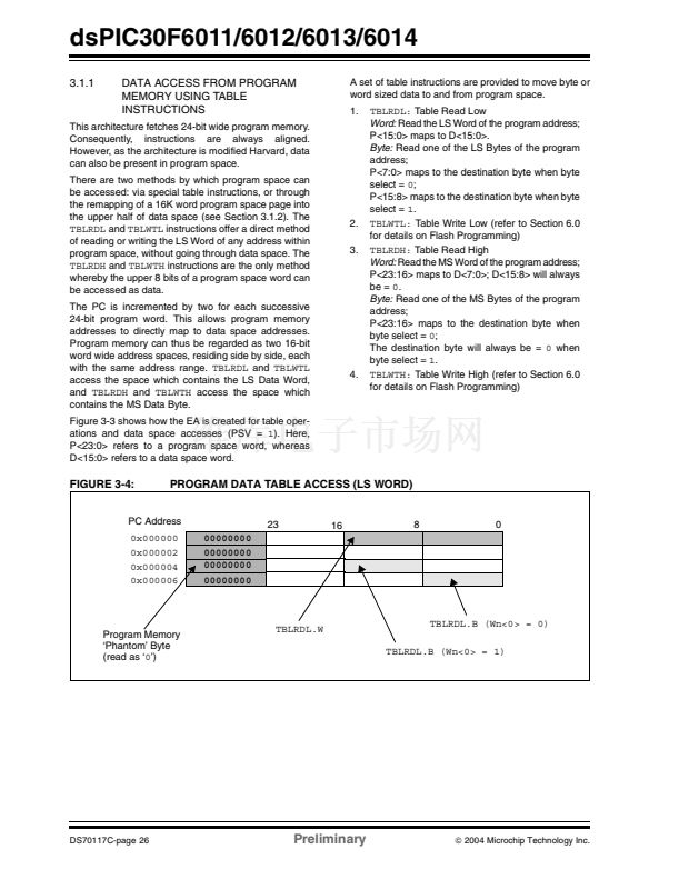
dsPIC30F6011/6012/6013/6014
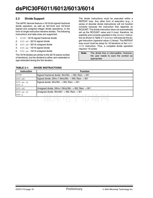
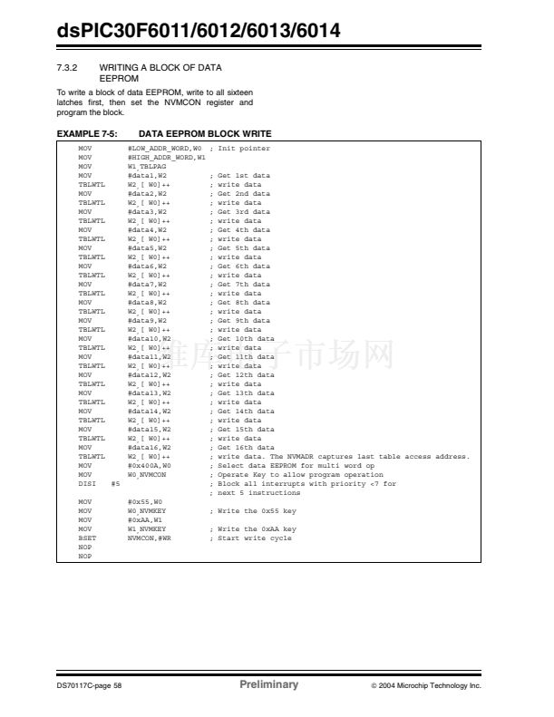
2.4.1
MULTIPLIER
2.4.2.1
The 17 x 17-bit multiplier is capable of signed or
unsigned operation and can multiplex its output using a
scaler to support either 1.31 fractional (Q31) or 32-bit
integer results. Unsigned operands are zero-extended
into the 17th bit of the multiplier input value. Signed
operands are sign-extended into the 17th bit of the mul-
tiplier input value. The output of the 17 x 17-bit multi-
plier/scaler is a 33-bit value which is sign-extended to
40 bits. Integer data is inherently represented as a
signed two鈥檚 complement value, where the MSB is
defined as a sign bit. Generally speaking, the range of
an N-bit two鈥檚 complement integer is -2
N-1
to 2
N-1
鈥?1.
For a 16-bit integer, the data range is -32768 (0x8000)
to 32767 (0x7FFF) including 鈥?鈥? For a 32-bit integer,
the data range is -2,147,483,648 (0x8000
0000)
to
2,147,483,645 (0x7FFF
FFFF).
When the multiplier is configured for fractional multipli-
cation, the data is represented as a two鈥檚 complement
fraction, where the MSB is defined as a sign bit and the
radix point is implied to lie just after the sign bit (QX for-
mat). The range of an N-bit two鈥檚 complement fraction
with this implied radix point is -1.0 to (1 鈥?2
1-N
). For a
16-bit fraction, the Q15 data range is -1.0 (0x8000) to
0.999969482 (0x7FFF) including 鈥?鈥?and has a preci-
sion of 3.01518x10
-5
. In Fractional mode, the 16x16
multiply operation generates a 1.31 product which has
a precision of 4.65661 x 10
-10
.
The same multiplier is used to support the MCU multi-
ply instructions which include integer 16-bit signed,
unsigned and mixed sign multiplies.
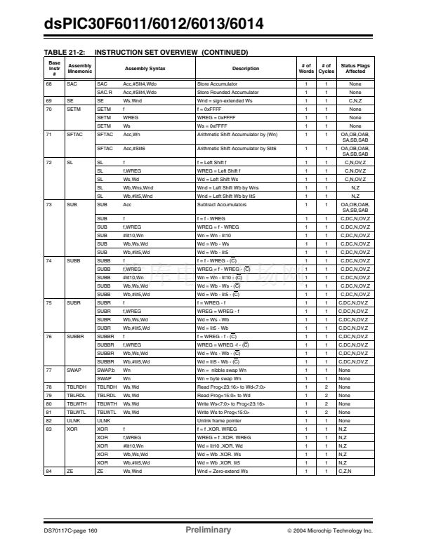
The
MUL
instruction may be directed to use byte or
word sized operands. Byte operands will direct a 16-bit
result, and word operands will direct a 32-bit result to
the specified register(s) in the W array.
Adder/Subtracter, Overflow and
Saturation
The adder/subtracter is a 40-bit adder with an optional
zero input into one side and either true, or complement
data into the other input. In the case of addition, the
carry/borrow input is active high and the other input is
true data (not complemented), whereas in the case of
subtraction, the carry/borrow input is active low and the
other input is complemented. The adder/subtracter
generates overflow status bits SA/SB and OA/OB,
which are latched and reflected in the STATUS register:
鈥?Overflow from bit 39: this is a catastrophic
overflow in which the sign of the accumulator is
destroyed.
鈥?Overflow into guard bits 32 through 39: this is a
recoverable overflow. This bit is set whenever all
the guard bits bits are not identical to each other.
The adder has an additional saturation block which
controls accumulator data saturation, if selected. It
uses the result of the adder, the overflow status bits
described above, and the SATA/B (CORCON<7:6>)
and ACCSAT (CORCON<4>) mode control bits to
determine when and to what value to saturate.
Six STATUS register bits have been provided to
support saturation and overflow; they are:
1.
2.
3.
OA:
AccA overflowed into guard bits
OB:
AccB overflowed into guard bits
SA:
AccA saturated (bit 31 overflow and saturation)
or
AccA overflowed into guard bits and saturated
(bit 39 overflow and saturation)
SB:
AccB saturated (bit 31 overflow and saturation)
or
AccB overflowed into guard bits and saturated
(bit 39 overflow and saturation)
OAB:
Logical OR of OA and OB
SAB:
Logical OR of SA and SB
2.4.2
DATA ACCUMULATORS AND
ADDER/SUBTRACTER
4.
The data accumulator consists of a 40-bit adder/
subtracter with automatic sign extension logic. It can
select one of two accumulators (A or B) as its pre-
accumulation source and post-accumulation destina-
tion. For the
ADD
and
LAC
instructions, the data to be
accumulated or loaded can be optionally scaled via the
barrel shifter, prior to accumulation.
5.
6.
The OA and OB bits are modified each time data
passes through the adder/subtracter. When set, they
indicate that the most recent operation has overflowed
into the accumulator guard bits (bits 32 through 39).
The OA and OB bits can also optionally generate an
arithmetic warning trap when set and the correspond-
ing overflow trap flag enable bit (OVATEN, OVBTEN) in
the INTCON1 register (refer to Section 5.0) is set. This
allows the user to take immediate action, for example,
to correct system gain.
铮?/div>
2004 Microchip Technology Inc.
Preliminary
DS70117C-page 19


 1
1
 2
2
 3
3
 4
4
 5
5
 6
6
 7
7
 8
8
 9
9
 10
10
 11
11
 12
12
 13
13
 14
14
 15
15
 16
16
 17
17
 18
18
 19
19
 20
20
 21
21
 22
22
 23
23
 24
24
 25
25
 26
26
 27
27
 28
28
 29
29
 30
30
 31
31
 32
32
 33
33
 34
34
 35
35
 36
36
 37
37
 38
38
 39
39
 40
40
 41
41
 42
42
 43
43
 44
44
 45
45
 46
46
 47
47
 48
48
 49
49
 50
50
 51
51
 52
52
 53
53
 54
54
 55
55
 56
56
 57
57
 58
58
 59
59
 60
60
 61
61
 62
62
 63
63
 64
64
 65
65
 66
66
 67
67
 68
68
 69
69
 70
70
 71
71
 72
72
 73
73
 74
74
 75
75
 76
76
 77
77
 78
78
 79
79
 80
80
 81
81
 82
82
 83
83
 84
84
 85
85
 86
86
 87
87
 88
88
 89
89
 90
90
 91
91
 92
92
 93
93
 94
94
 95
95
 96
96
 97
97
 98
98
 99
99
 100
100
 101
101
 102
102
 103
103
 104
104
 105
105
 106
106
 107
107
 108
108
 109
109
 110
110
 111
111
 112
112
 113
113
 114
114
 115
115
 116
116
 117
117
 118
118
 119
119
 120
120
 121
121
 122
122
 123
123
 124
124
 125
125
 126
126
 127
127
 128
128
 129
129
 130
130
 131
131
 132
132
 133
133
 134
134
 135
135
 136
136
 137
137
 138
138
 139
139
 140
140
 141
141
 142
142
 143
143
 144
144
 145
145
 146
146
 147
147
 148
148
 149
149
 150
150
 151
151
 152
152
 153
153
 154
154
 155
155
 156
156
 157
157
 158
158
 159
159
 160
160
 161
161
 162
162
 163
163
 164
164
 165
165
 166
166
 167
167
 168
168
 169
169
 170
170
 171
171
 172
172
 173
173
 174
174
 175
175
 176
176
 177
177
 178
178
 179
179
 180
180
 181
181
 182
182
 183
183
 184
184
 185
185
 186
186
 187
187
 188
188
 189
189
 190
190
 191
191
 192
192
 193
193
 194
194
 195
195
 196
196
 197
197
 198
198
 199
199
 200
200
 201
201
 202
202
 203
203
 204
204
 205
205
 206
206
 207
207
 208
208
 209
209
 210
210
 211
211
 212
212
 213
213
 214
214
 215
215
 216
216
 217
217
 218
218
 219
219
 220
220
 221
221
 222
222
