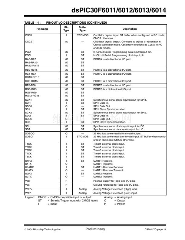
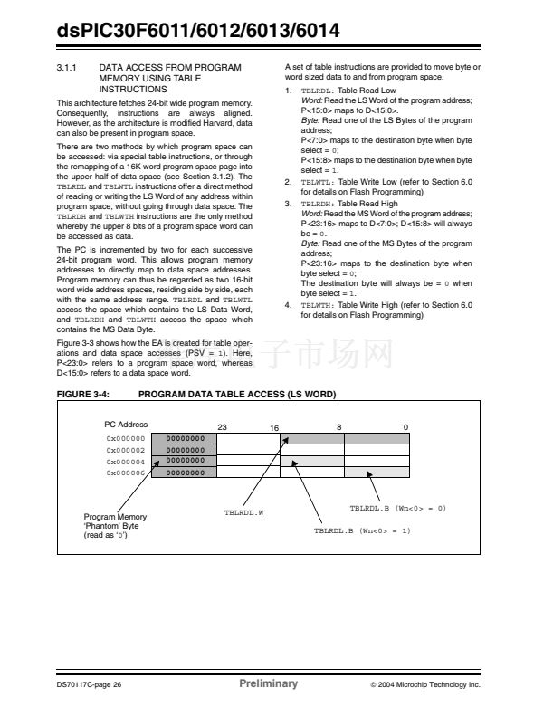
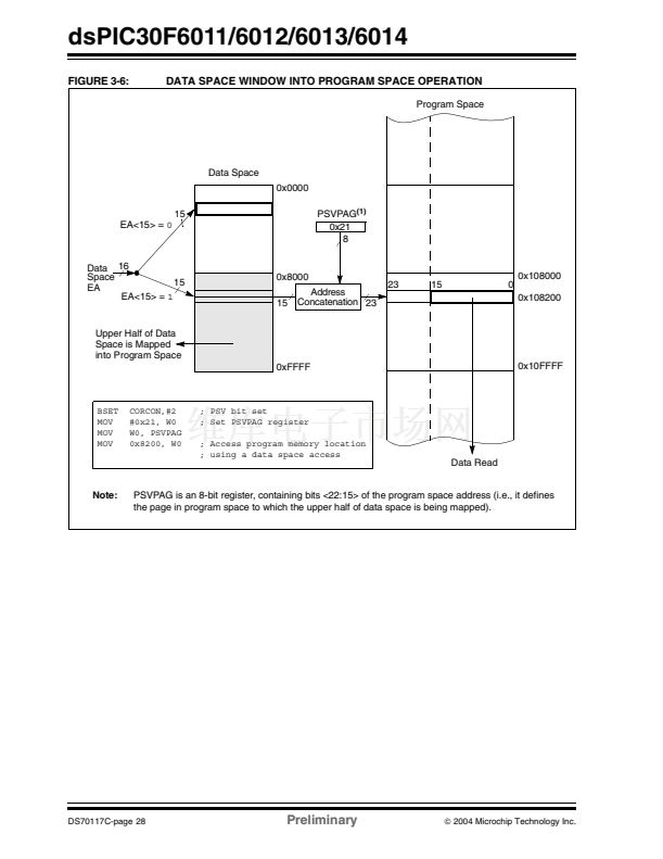
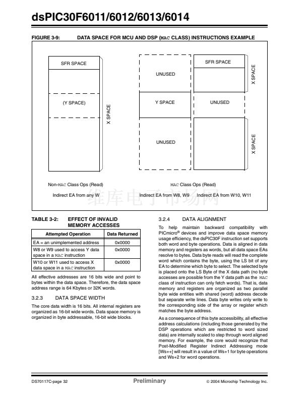
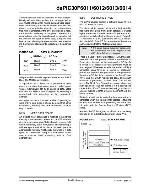
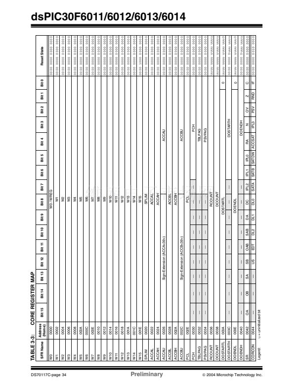
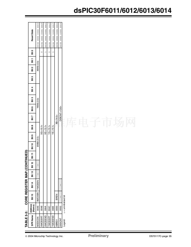
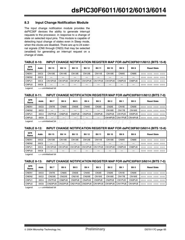
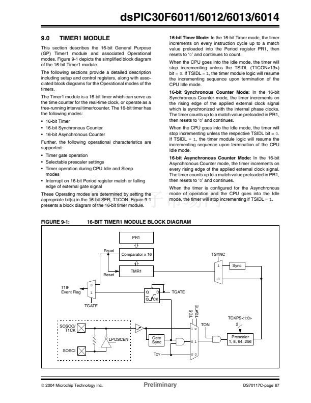
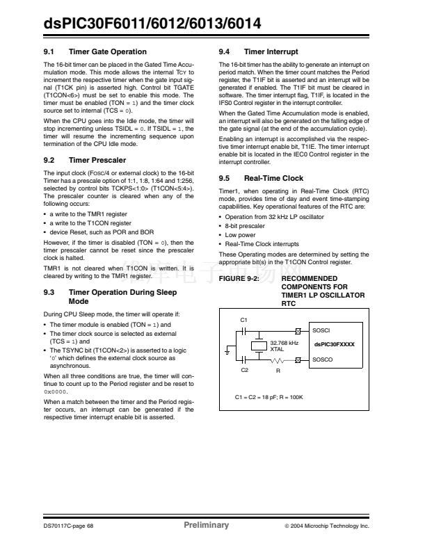
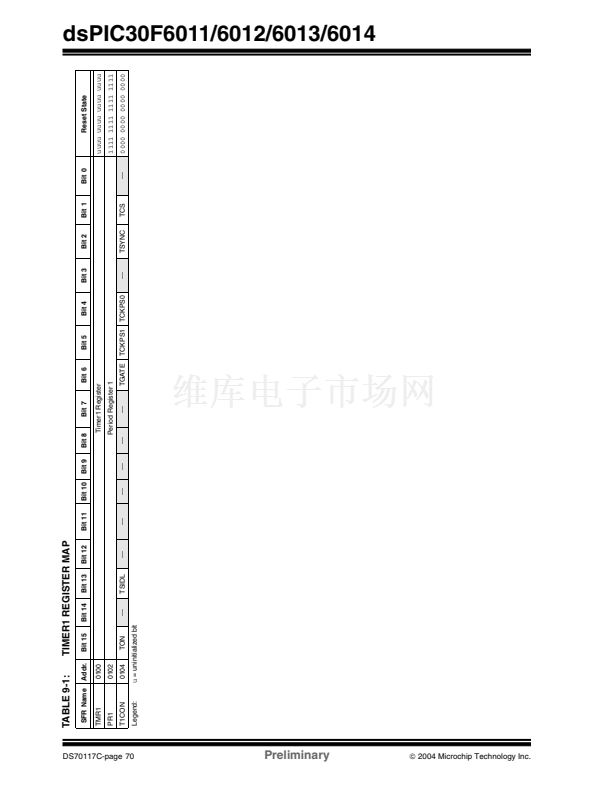
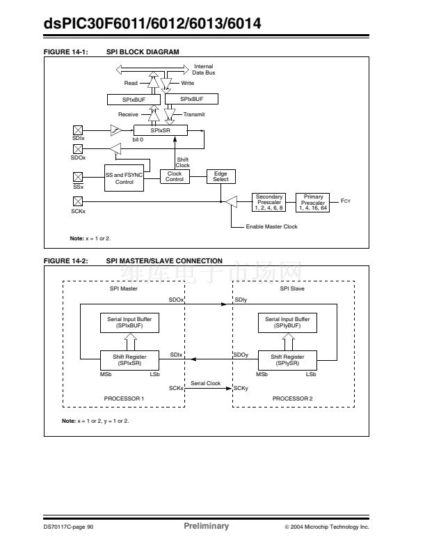
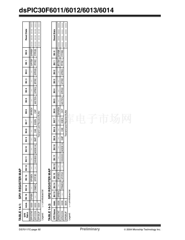
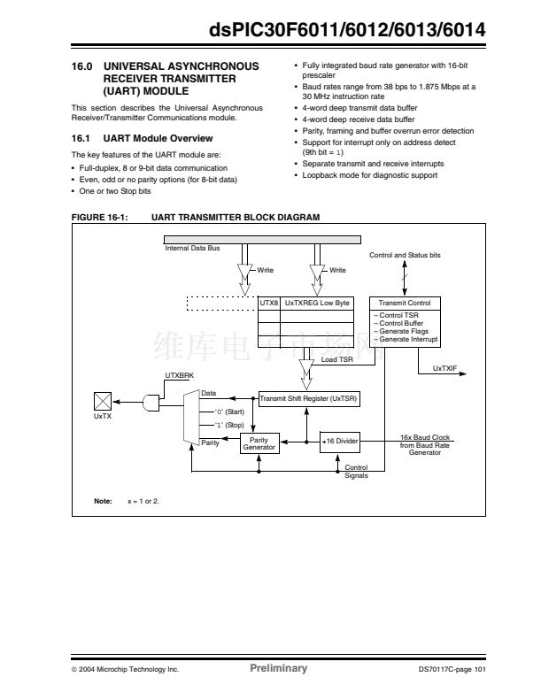
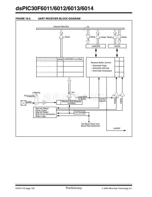
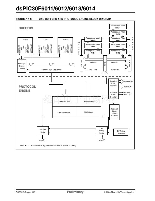
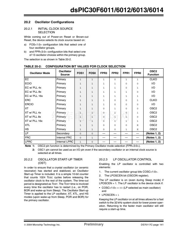
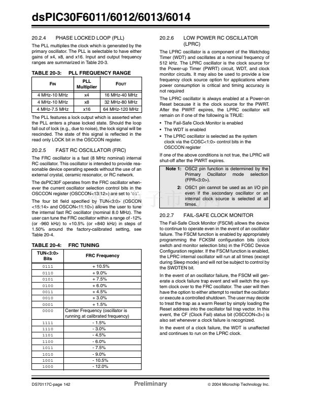
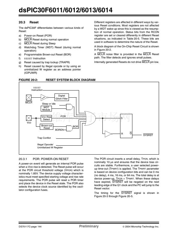
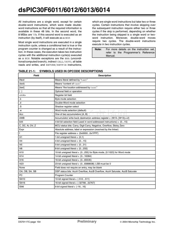
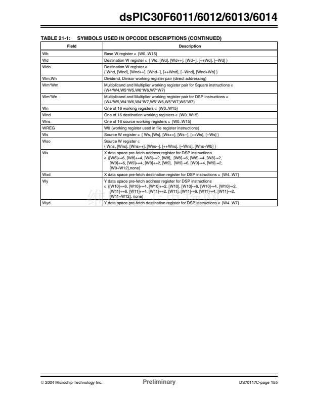
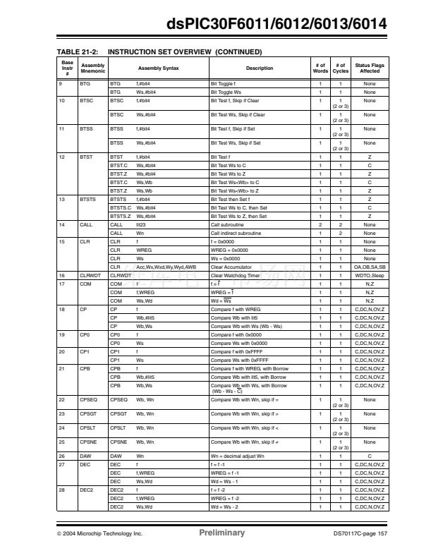
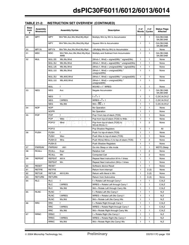
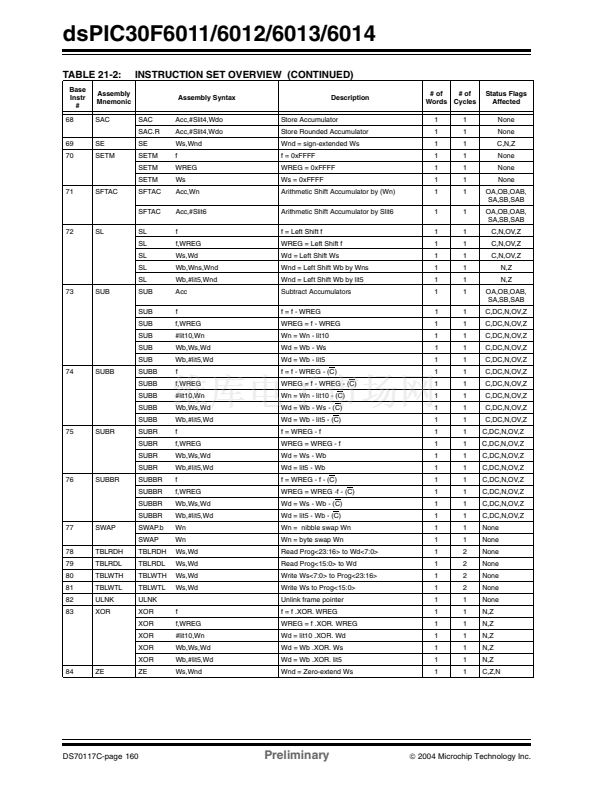
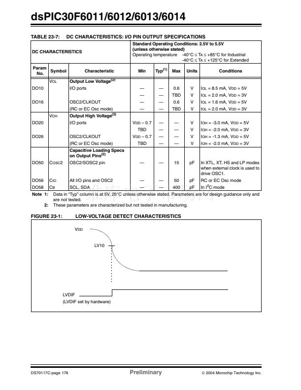
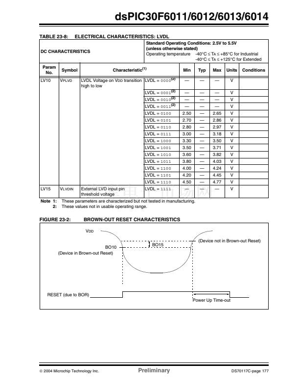
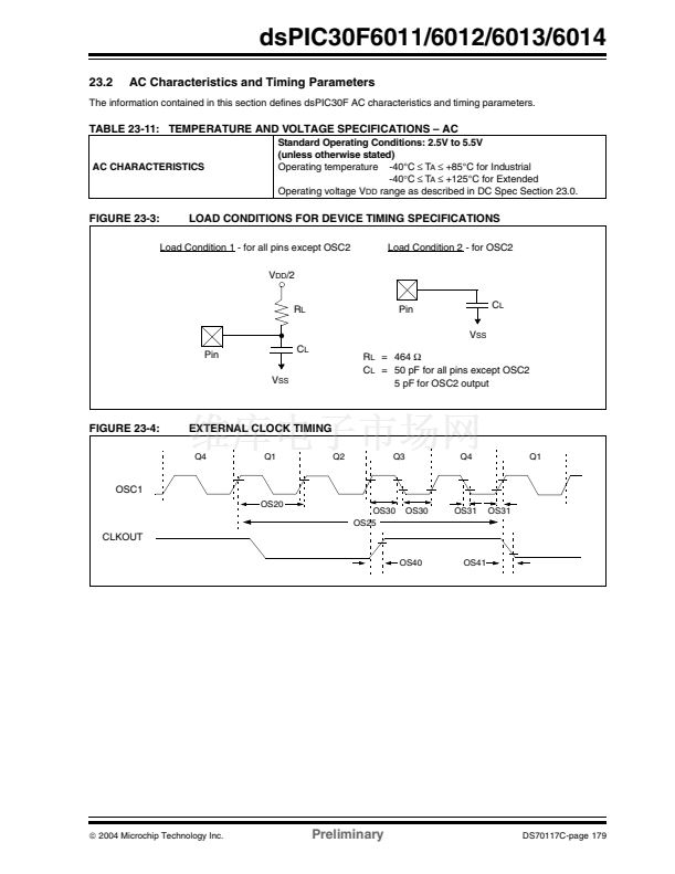
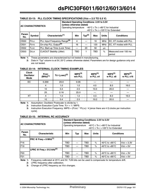
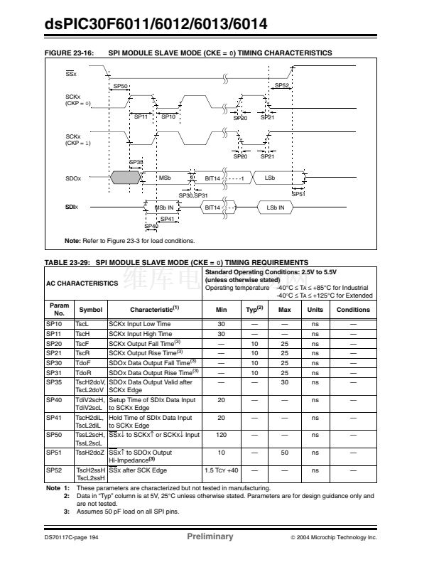
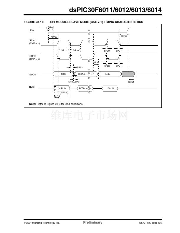
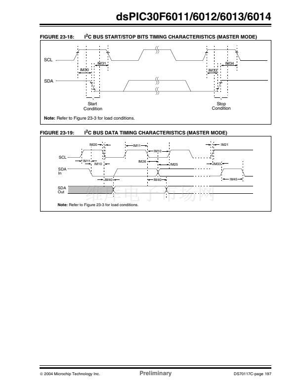
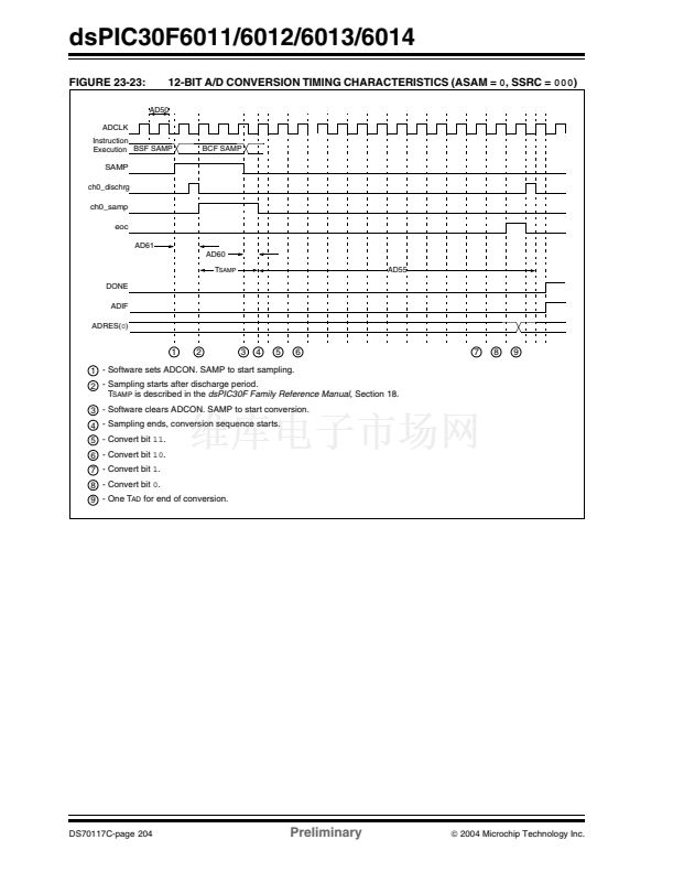
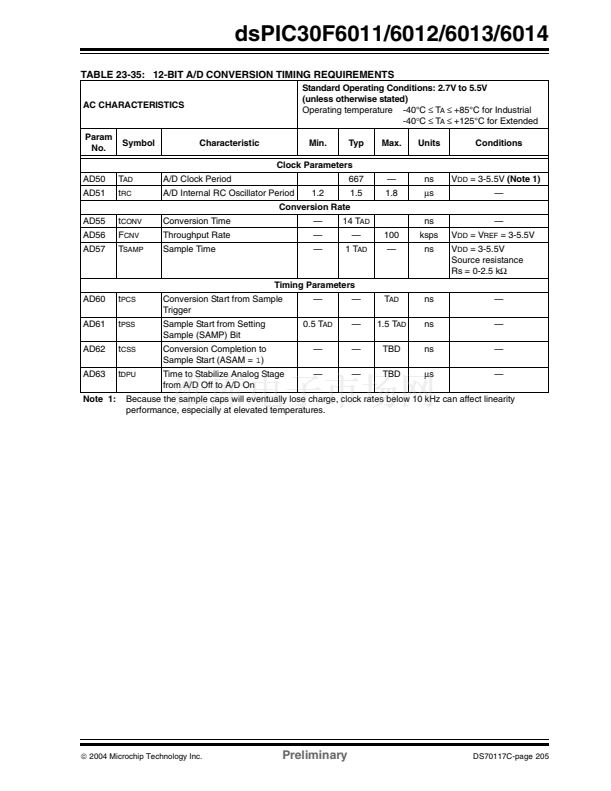
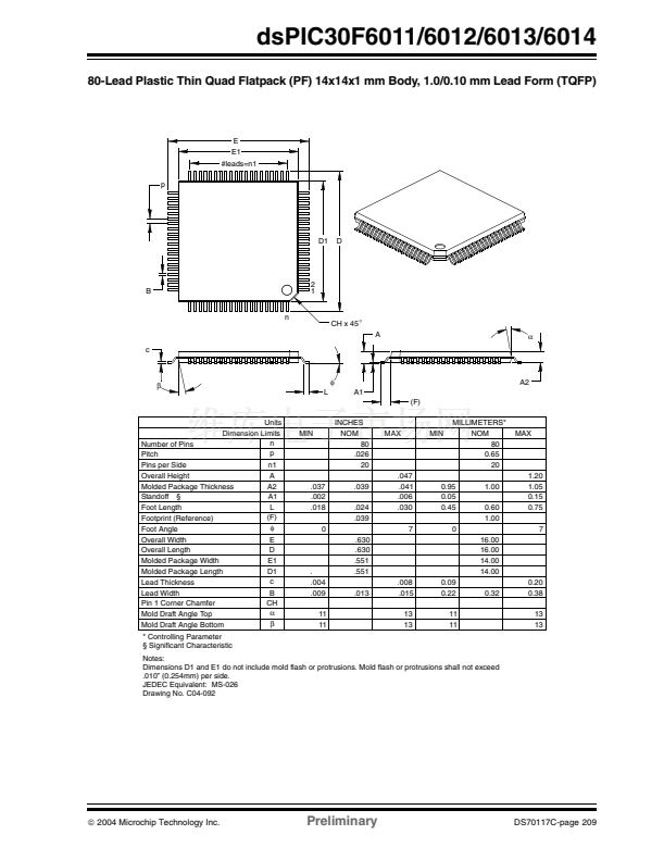
dsPIC30F6011/6012/6013/6014
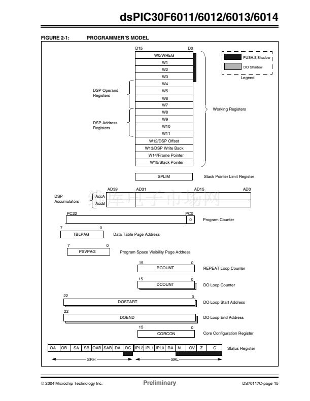
The SA and SB bits are modified each time data
passes through the adder/subtracter but can only be
cleared by the user. When set, they indicate that the
accumulator has overflowed its maximum range (bit 31
for 32-bit saturation, or bit 39 for 40-bit saturation) and
will be saturated (if saturation is enabled). When satu-
ration is not enabled, SA and SB default to bit 39 over-
flow and thus indicate that a catastrophic overflow has
occurred. If the COVTE bit in the INTCON1 register is
set, SA and SB bits will generate an arithmetic warning
trap when saturation is disabled.
The overflow and saturation status bits can optionally
be viewed in the STATUS register (SR) as the logical
OR of OA and OB (in bit OAB) and the logical OR of SA
and SB (in bit SAB). This allows programmers to check
one bit in the STATUS register to determine if either
accumulator has overflowed, or one bit to determine if
either accumulator has saturated. This would be useful
for complex number arithmetic which typically uses
both the accumulators.
The device supports three saturation and overflow
modes:
1.
Bit 39 Overflow and Saturation:
When bit 39 overflow and saturation occurs, the
saturation logic loads the maximally positive 9.31
(0x7FFFFFFFFF), or maximally negative 9.31
value (0x8000000000) into the target accumula-
tor. The SA or SB bit is set and remains set until
cleared by the user. This is referred to as 鈥榮uper
saturation鈥?and provides protection against erro-
neous data, or unexpected algorithm problems
(e.g., gain calculations).
Bit 31 Overflow and Saturation:
When bit 31 overflow and saturation occurs, the
saturation logic then loads the maximally posi-
tive 1.31 value (0x007FFFFFFF), or maximally
negative 1.31 value (0x0080000000) into the
target accumulator. The SA or SB bit is set and
remains set until cleared by the user. When this
Saturation mode is in effect, the guard bits are
not used (so the OA, OB or OAB bits are never
set).
Bit 39 Catastrophic Overflow:
The bit 39 overflow status bit from the adder is
used to set the SA or SB bit which remain set
until cleared by the user. No saturation operation
is performed and the accumulator is allowed to
overflow (destroying its sign). If the COVTE bit in
the INTCON1 register is set, a catastrophic
overflow can initiate a trap exception.
2.4.2.2
Accumulator 鈥榃rite Back鈥?/div>
The
MAC
class of instructions (with the exception of
MPY, MPY.N, ED
and
EDAC)
can optionally write a
rounded version of the high word (bits 31 through 16)
of the accumulator that is not targeted by the instruction
into data space memory. The write is performed across
the X bus into combined X and Y address space. The
following Addressing modes are supported:
1.
W13, Register Direct:
The rounded contents of the non-target
accumulator are written into W13 as a 1.15
fraction.
[W13]+=2, Register Indirect with Post-Increment:
The rounded contents of the non-target accumu-
lator are written into the address pointed to by
W13 as a 1.15 fraction. W13 is then
incremented by 2 (for a word write).
2.
2.4.2.3
Round Logic
The round logic is a combinational block which per-
forms a conventional (biased) or convergent (unbi-
ased) round function during an accumulator write
(store). The Round mode is determined by the state of
the RND bit in the CORCON register. It generates a 16-
bit, 1.15 data value which is passed to the data space
write saturation logic. If rounding is not indicated by the
instruction, a truncated 1.15 data value is stored and
the LS Word is simply discarded.
Conventional rounding takes bit 15 of the accumulator,
zero-extends it and adds it to the ACCxH word (bits 16
through 31 of the accumulator). If the ACCxL word
(bits 0 through 15 of the accumulator) is between
0x8000 and 0xFFFF (0x8000 included), ACCxH is
incremented. If ACCxL is between 0x0000 and 0x7FFF,
ACCxH is left unchanged. A consequence of this
algorithm is that over a succession of random rounding
operations, the value will tend to be biased slightly
positive.
Convergent (or unbiased) rounding operates in the
same manner as conventional rounding, except when
ACCxL equals 0x8000. If this is the case, the LS bit
(bit 16 of the accumulator) of ACCxH is examined. If it
is 鈥?鈥? ACCxH is incremented. If it is 鈥?鈥? ACCxH is not
modified. Assuming that bit 16 is effectively random in
nature, this scheme will remove any rounding bias that
may accumulate.
The
SAC
and
SAC.R
instructions store either a trun-
cated (SAC) or rounded (SAC.R) version of the contents
of the target accumulator to data memory via the X bus
(subject to data saturation, see Section 2.4.2.4). Note
that for the
MAC
class of instructions, the accumulator
write back operation will function in the same manner,
addressing combined MCU (X and Y) data space
though the X bus. For this class of instructions, the data
is always subject to rounding.
2.
3.
DS70117C-page 20
Preliminary
铮?/div>
2004 Microchip Technology Inc.


 1
1
 2
2
 3
3
 4
4
 5
5
 6
6
 7
7
 8
8
 9
9
 10
10
 11
11
 12
12
 13
13
 14
14
 15
15
 16
16
 17
17
 18
18
 19
19
 20
20
 21
21
 22
22
 23
23
 24
24
 25
25
 26
26
 27
27
 28
28
 29
29
 30
30
 31
31
 32
32
 33
33
 34
34
 35
35
 36
36
 37
37
 38
38
 39
39
 40
40
 41
41
 42
42
 43
43
 44
44
 45
45
 46
46
 47
47
 48
48
 49
49
 50
50
 51
51
 52
52
 53
53
 54
54
 55
55
 56
56
 57
57
 58
58
 59
59
 60
60
 61
61
 62
62
 63
63
 64
64
 65
65
 66
66
 67
67
 68
68
 69
69
 70
70
 71
71
 72
72
 73
73
 74
74
 75
75
 76
76
 77
77
 78
78
 79
79
 80
80
 81
81
 82
82
 83
83
 84
84
 85
85
 86
86
 87
87
 88
88
 89
89
 90
90
 91
91
 92
92
 93
93
 94
94
 95
95
 96
96
 97
97
 98
98
 99
99
 100
100
 101
101
 102
102
 103
103
 104
104
 105
105
 106
106
 107
107
 108
108
 109
109
 110
110
 111
111
 112
112
 113
113
 114
114
 115
115
 116
116
 117
117
 118
118
 119
119
 120
120
 121
121
 122
122
 123
123
 124
124
 125
125
 126
126
 127
127
 128
128
 129
129
 130
130
 131
131
 132
132
 133
133
 134
134
 135
135
 136
136
 137
137
 138
138
 139
139
 140
140
 141
141
 142
142
 143
143
 144
144
 145
145
 146
146
 147
147
 148
148
 149
149
 150
150
 151
151
 152
152
 153
153
 154
154
 155
155
 156
156
 157
157
 158
158
 159
159
 160
160
 161
161
 162
162
 163
163
 164
164
 165
165
 166
166
 167
167
 168
168
 169
169
 170
170
 171
171
 172
172
 173
173
 174
174
 175
175
 176
176
 177
177
 178
178
 179
179
 180
180
 181
181
 182
182
 183
183
 184
184
 185
185
 186
186
 187
187
 188
188
 189
189
 190
190
 191
191
 192
192
 193
193
 194
194
 195
195
 196
196
 197
197
 198
198
 199
199
 200
200
 201
201
 202
202
 203
203
 204
204
 205
205
 206
206
 207
207
 208
208
 209
209
 210
210
 211
211
 212
212
 213
213
 214
214
 215
215
 216
216
 217
217
 218
218
 219
219
 220
220
 221
221
 222
222
