鈥?/div>
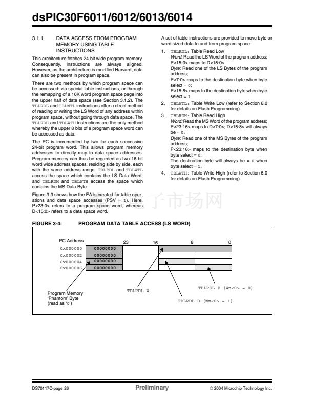
Timer2 and Timer3 Selection mode
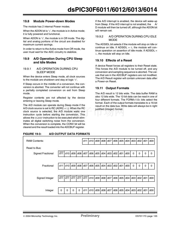
Simple Output Compare Match mode
Dual Output Compare Match mode
Simple PWM mode
Output Compare During Sleep and Idle modes
Interrupt on Output Compare/PWM Event
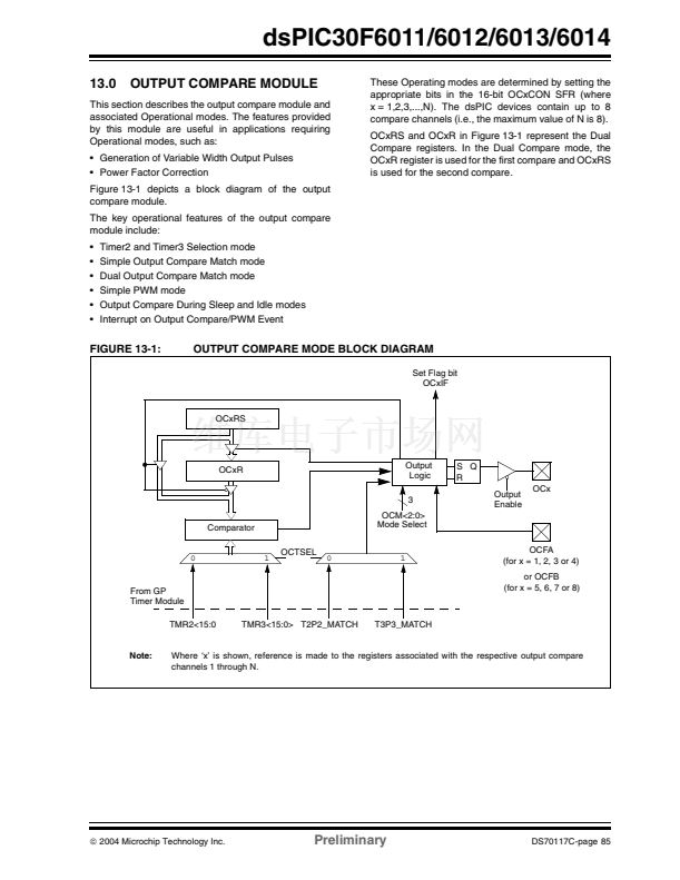
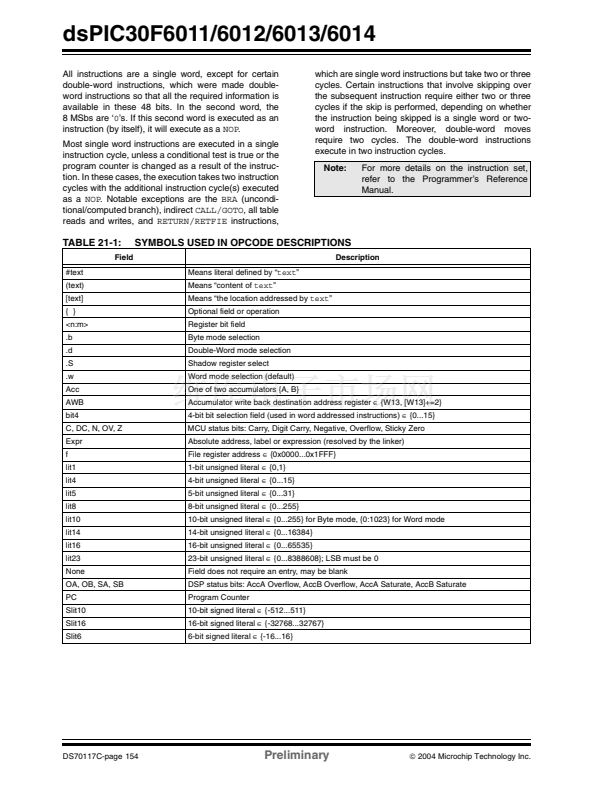
These Operating modes are determined by setting the
appropriate bits in the 16-bit OCxCON SFR (where
x = 1,2,3,...,N). The dsPIC devices contain up to 8
compare channels (i.e., the maximum value of N is 8).
OCxRS and OCxR in Figure 13-1 represent the Dual
Compare registers. In the Dual Compare mode, the
OCxR register is used for the first compare and OCxRS
is used for the second compare.
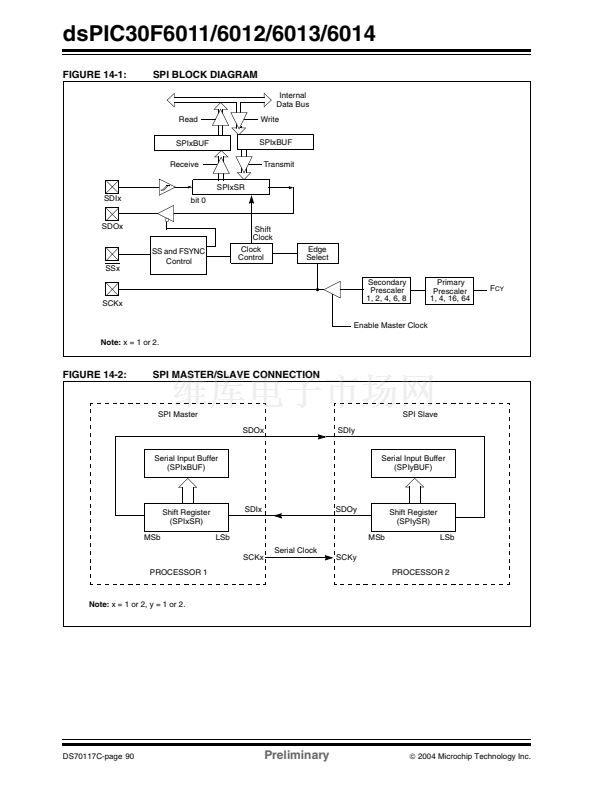
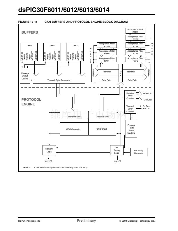
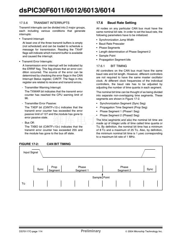
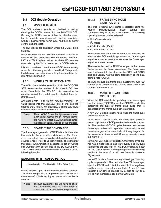
FIGURE 13-1:
OUTPUT COMPARE MODE BLOCK DIAGRAM
Set Flag bit
OCxIF
OCxRS
OCxR
Output
Logic
3
S Q
R
Output
Enable
OCx
Comparator
OCTSEL
OCM<2:0>
Mode Select
OCFA
(for x = 1, 2, 3 or 4)
or OCFB
(for x = 5, 6, 7 or 8)
0
1
0
1
From GP
Timer Module
TMR2<15:0
TMR3<15:0> T2P2_MATCH
T3P3_MATCH
Note:
Where 鈥榵鈥?is shown, reference is made to the registers associated with the respective output compare
channels 1 through N.
铮?/div>
2004 Microchip Technology Inc.
Preliminary
DS70117C-page 85


 1
1
 2
2
 3
3
 4
4
 5
5
 6
6
 7
7
 8
8
 9
9
 10
10
 11
11
 12
12
 13
13
 14
14
 15
15
 16
16
 17
17
 18
18
 19
19
 20
20
 21
21
 22
22
 23
23
 24
24
 25
25
 26
26
 27
27
 28
28
 29
29
 30
30
 31
31
 32
32
 33
33
 34
34
 35
35
 36
36
 37
37
 38
38
 39
39
 40
40
 41
41
 42
42
 43
43
 44
44
 45
45
 46
46
 47
47
 48
48
 49
49
 50
50
 51
51
 52
52
 53
53
 54
54
 55
55
 56
56
 57
57
 58
58
 59
59
 60
60
 61
61
 62
62
 63
63
 64
64
 65
65
 66
66
 67
67
 68
68
 69
69
 70
70
 71
71
 72
72
 73
73
 74
74
 75
75
 76
76
 77
77
 78
78
 79
79
 80
80
 81
81
 82
82
 83
83
 84
84
 85
85
 86
86
 87
87
 88
88
 89
89
 90
90
 91
91
 92
92
 93
93
 94
94
 95
95
 96
96
 97
97
 98
98
 99
99
 100
100
 101
101
 102
102
 103
103
 104
104
 105
105
 106
106
 107
107
 108
108
 109
109
 110
110
 111
111
 112
112
 113
113
 114
114
 115
115
 116
116
 117
117
 118
118
 119
119
 120
120
 121
121
 122
122
 123
123
 124
124
 125
125
 126
126
 127
127
 128
128
 129
129
 130
130
 131
131
 132
132
 133
133
 134
134
 135
135
 136
136
 137
137
 138
138
 139
139
 140
140
 141
141
 142
142
 143
143
 144
144
 145
145
 146
146
 147
147
 148
148
 149
149
 150
150
 151
151
 152
152
 153
153
 154
154
 155
155
 156
156
 157
157
 158
158
 159
159
 160
160
 161
161
 162
162
 163
163
 164
164
 165
165
 166
166
 167
167
 168
168
 169
169
 170
170
 171
171
 172
172
 173
173
 174
174
 175
175
 176
176
 177
177
 178
178
 179
179
 180
180
 181
181
 182
182
 183
183
 184
184
 185
185
 186
186
 187
187
 188
188
 189
189
 190
190
 191
191
 192
192
 193
193
 194
194
 195
195
 196
196
 197
197
 198
198
 199
199
 200
200
 201
201
 202
202
 203
203
 204
204
 205
205
 206
206
 207
207
 208
208
 209
209
 210
210
 211
211
 212
212
 213
213
 214
214
 215
215
 216
216
 217
217
 218
218
 219
219
 220
220
 221
221
 222
222
