Philips Semiconductors
Product data
14-bit SSTL_2 registered driver
with differential clock inputs
SSTV16857
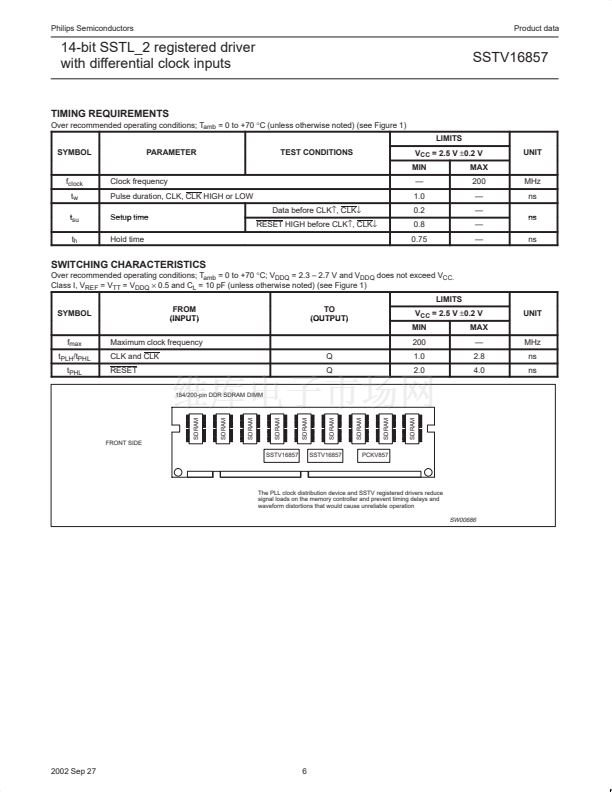
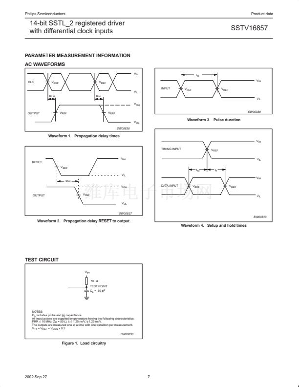
PARAMETER MEASUREMENT INFORMATION
AC WAVEFORMS
V
IH
CLK
V
REF
V
REF
INPUT
V
IL
t
PLH
t
PHL
V
OH
OUTPUT
V
REF
V
REF
V
OL
V
REF
V
REF
V
IL
t
W
V
IH
SW00339
Waveform 3. Pulse duration
SW00836
Waveform 1. Propagation delay times
V
IH
TIMING INPUT
V
IH
RESET
V
REF
V
IL
t
PHL
V
OH
OUTPUT
V
REF
V
OL
DATA INPUT
V
REF
V
REF
V
IL
t
su
t
h
V
IH
V
REF
V
IL
SW00837
SW00340
Waveform 2. Propagation delay RESET to output.
Waveform 4. Setup and hold times
TEST CIRCUIT
V
TT
50 鈩?/div>
TEST POINT
C
L
= 30 pF
NOTES:
C
L
includes probe and jig capacitance
All input pulses are supplied by generators having the following characteristics:
PRR
鈮?/div>
10 MHz, Z
O
= 50
鈩?
t
r
鈮?/div>
1.25 ns/V, t
f
1.25 ns/V.
The outputs are measured one at a time with one transition per measurement.
V
TT
= V
REF
= V
DDQ
x 0.5
SW00838
Figure 1. Load circuitry
2002 Sep 27
7


 1
1
 2
2
 3
3
 4
4
 5
5
 6
6
 7
7
 8
8
 9
9
 10
10
 11
11
 12
12
