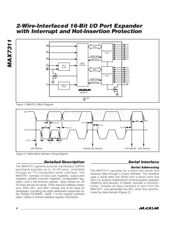
2-Wire-Interfaced 16-Bit I/O Port Expander
with Interrupt and Hot-Insertion Protection
Eight of the MAX7311鈥檚 nine registers are configured to
operate as four register pairs: input ports, output ports,
polarity inversion ports, and configuration ports. After
sending 1 byte of data to one register, the next byte is
sent to the other register in the pair. For example, if the
first byte of data is sent to output port 2, then the next
byte of data is stored in output port 1. An unlimited
number of data bytes can be sent in one write transmis-
sion. This allows each 8-bit register to be updated inde-
pendently of the other registers.
ACKNOWLEDGE
FROM SLAVE
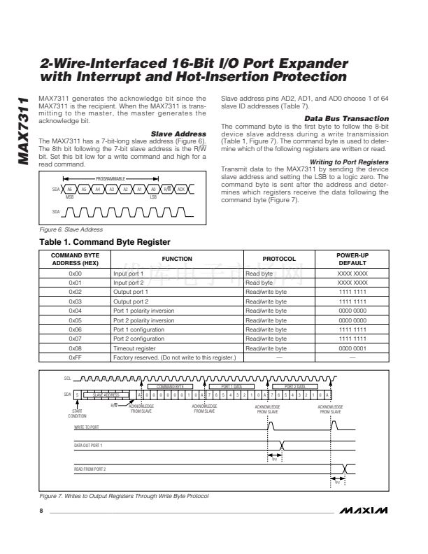
Reading Port Registers
To read the device data, the bus master must first send
the MAX7311 address with the R/W bit set to zero, fol-
lowed by the command byte, which determines which
register is accessed. After a restart, the bus master
must then send the MAX7311 address with the R/W bit
set to 1. Data from the register defined by the com-
mand byte is then sent from the MAX7311 to the master
(Figures 8, 9).
MAX7311
DATA FROM LOWER OR
UPPER BYTE OF REGISTER
DATA FROM LOWER OR
UPPER BYTE OF REGISTER
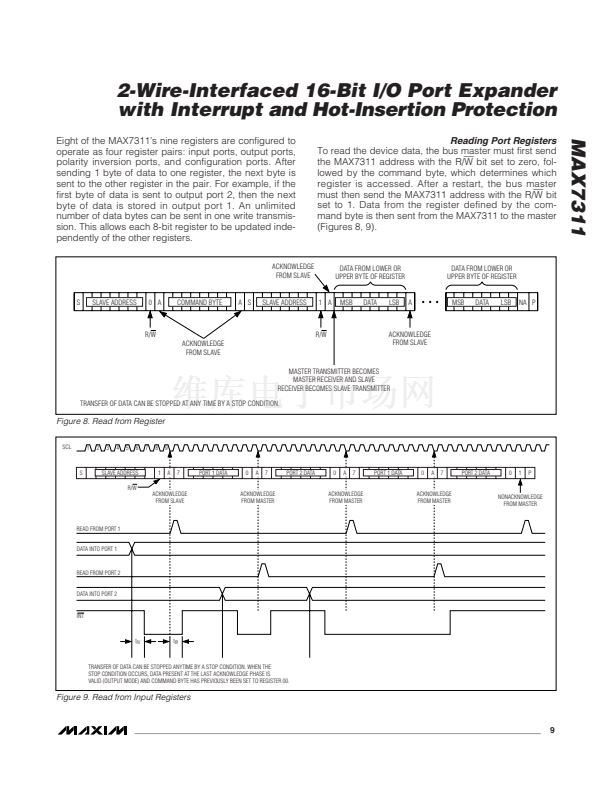
S
SLAVE ADDRESS
0 A
COMMAND BYTE
A S
SLAVE ADDRESS
1 A
MSB
DATA
LSB
A
MSB
DATA
LSB
NA P
R/W
ACKNOWLEDGE
FROM SLAVE
R/W
ACKNOWLEDGE
FROM SLAVE
MASTER TRANSMITTER BECOMES
MASTER RECEIVER AND SLAVE
RECEIVER BECOMES SLAVE TRANSMITTER
TRANSFER OF DATA CAN BE STOPPED AT ANY TIME BY A STOP CONDITION.
Figure 8. Read from Register
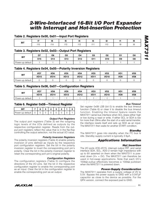
SCL
1
2
3
4
5
6
7
8
9
S
SLAVE ADDRESS
R/W
1
A
7
PORT 1 DATA
0
A
7
PORT 2 DATA
0
A
7
PORT 1 DATA
0
A
7
PORT 2 DATA
0
1
P
ACKNOWLEDGE
FROM SLAVE
ACKNOWLEDGE
FROM MASTER
ACKNOWLEDGE
FROM MASTER
ACKNOWLEDGE
FROM MASTER
NONACKNOWLEDGE
FROM MASTER
READ FROM PORT 1
DATA INTO PORT 1
READ FROM PORT 2
DATA INTO PORT 2
INT
t
IV
t
IR
TRANSFER OF DATA CAN BE STOPPED ANYTIME BY A STOP CONDITION. WHEN THE
STOP CONDITION OCCURS, DATA PRESENT AT THE LAST ACKNOWLEDGE PHASE IS
VALID (OUTPUT MODE) AND COMMAND BYTE HAS PREVIOUSLY BEEN SET TO REGISTER 00.
Figure 9. Read from Input Registers
_______________________________________________________________________________________
9


 1
1
 2
2
 3
3
 4
4
 5
5
 6
6
 7
7
 8
8
 9
9
 10
10
 11
11
 12
12
 13
13
 14
14
 15
15
 16
16
