2-Wire-Interfaced 16-Bit I/O Port Expander
with Interrupt and Hot-Insertion Protection
MAX7311
AD0
8 BIT
INPUT/OUTPUT
PORT 1
WRITE PULSE
AD2
SMBus
CONTROL
8 BIT
INPUT/OUTPUT
PORT 2
WRITE PULSE
V
+
READ PULSE
POWER-ON
RESET
I/O8
I/O9
I/O10
I/O11
I/O12
I/O13
I/O14
I/O15
INT
READ PULSE
I/O0
I/O1
I/O2
I/O3
I/O4
I/O5
I/O6
I/O7
AD1
SCL
SDA
INPUT
FILTER
N
MAX7311
GND
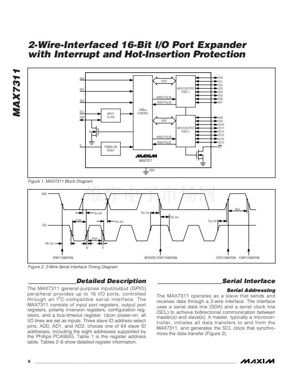
Figure 1. MAX7311 Block Diagram
SDA
t
BUF
t
SU, DAT
t
LOW
SCL
t
HD, DAT
t
SU, STA
t
HD, STA
t
SU, STO
t
HIGH
t
HD, STA
t
R
START CONDITION
t
F
REPEATED START CONDITION
STOP CONDITION
START CONDITION
Figure 2. 2-Wire Serial Interface Timing Diagram
Detailed Description
The MAX7311 general-purpose input/output (GPIO)
peripheral provides up to 16 I/O ports, controlled
through an I
2
C-compatible serial interface. The
MAX7311 consists of input port registers, output port
registers, polarity inversion registers, configuration reg-
isters, and a bus-timeout register. Upon power-on, all
I/O lines are set as inputs. Three slave ID address select
pins, AD0, AD1, and AD2, choose one of 64 slave ID
addresses, including the eight addresses supported by
the Phillips PCA9555. Table 1 is the register address
table. Tables 2鈥? show detailed register information.
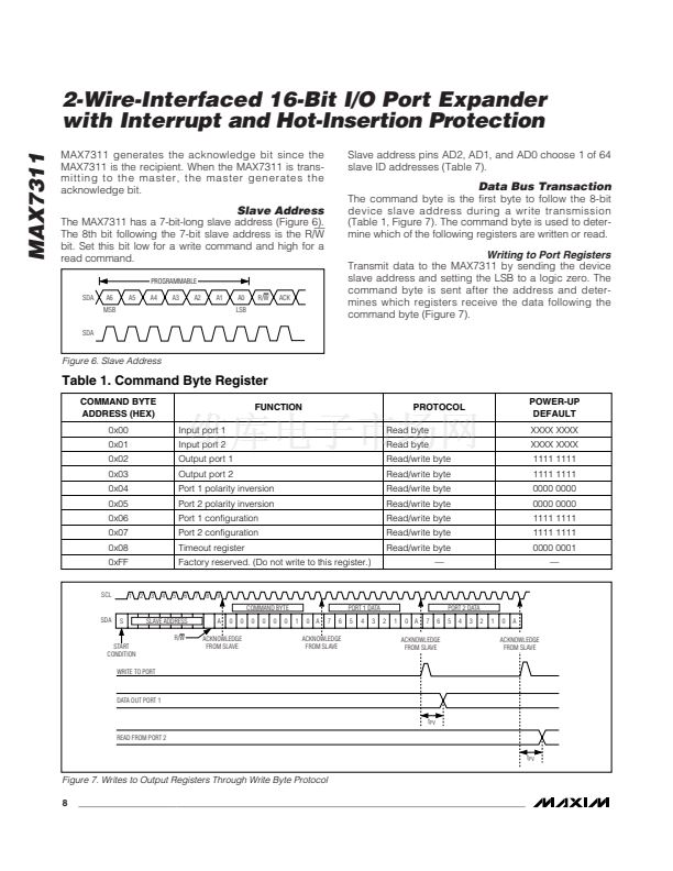
Serial Interface
Serial Addressing
The MAX7311 operates as a slave that sends and
receives data through a 2-wire interface. The interface
uses a serial data line (SDA) and a serial clock line
(SCL) to achieve bidirectional communication between
master(s) and slave(s). A master, typically a microcon-
troller, initiates all data transfers to and from the
MAX7311, and generates the SCL clock that synchro-
nizes the data transfer (Figure 2).
6
_______________________________________________________________________________________


 1
1
 2
2
 3
3
 4
4
 5
5
 6
6
 7
7
 8
8
 9
9
 10
10
 11
11
 12
12
 13
13
 14
14
 15
15
 16
16
