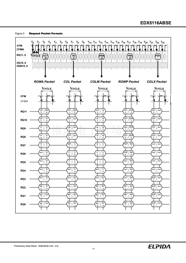
EDX5116ABSE
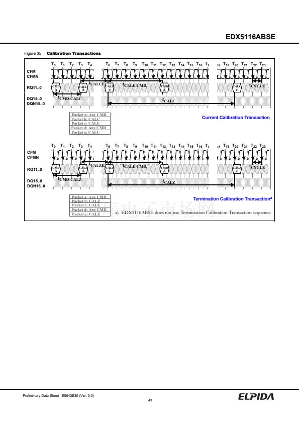
Calibration Transactions
Figure 35 shows the calibration transaction diagrams for the
XDR DRAM device. There is one calibration operation sup-
ported: calibration of the output current level I
OL
for each
DQi and DQNi pin.
The output current calibration sequence is shown in the upper
diagram. It begins when a period of t
CMD-CALC
is observed
after the last RQ packet (with command 鈥淐MD a鈥?in this
example). No request packets should be issued in this period.
A COLX packet with a鈥滳ALC b鈥?command is then issued to
start the current calibration sequence. A period of t
CALCE
is
observed after this packet. No request packets should be issued
during this period.
A COLX packet with a 鈥淐ALE c鈥?command is then issued to
end the current calibration sequence. A period of t
CALE-CMD
is
observed after this packet. No request packets should be issued
during this period. The first request packet may then be issued
(with command 鈥淐MD d鈥?in this example).
A second current calibration sequence must be started within
an interval of t
CALC
. In this example, the next COLX packet
with a 鈥淐ALC e鈥?command starts a subsequent sequence.
The dynamic termination calibration sequence is shown in the
lower diagram. Note that this memory component does not
use this sequence; termination calibration is performed during
the manufacturing process. However, the termination sequence
shown will be issued by the controller for those memory com-
ponents which do use a periodic calibration mechanism.
It begins when a period of t
CMD-CALZ
is observed after the
packet at edge T
0
(with command CMDa in this example). No
request packets should be issued in this period.
A COLX packet with a CALZ command is then issued at edge
T
3
to start the termination calibration sequence. A second
period of t
CALZE
is observed after this packet. No request
packets should be issued during this period.
A COLX packet with a CALE command is then issued at edge
T
6
to end the termination calibration sequence. A third period
of t
CALE-CMD
is observed after this packet. No request packets
should be issued during this period. The first request packet
may be issued at edge T
12
(with command CMDd in this exam-
ple).
A second termination calibration sequence must be started
within an interval of t
CALZ
. In this example, the next COLX
packet with a CALZ command occurs at edge T
20
.
Note that the labels for the CFM clock edges (of the form T
i
)
are not to scale, and are used to identify events in the diagrams.
Preliminary Data Sheet E0643E30 (Ver. 3.0)
42


 1
1
 2
2
 3
3
 4
4
 5
5
 6
6
 7
7
 8
8
 9
9
 10
10
 11
11
 12
12
 13
13
 14
14
 15
15
 16
16
 17
17
 18
18
 19
19
 20
20
 21
21
 22
22
 23
23
 24
24
 25
25
 26
26
 27
27
 28
28
 29
29
 30
30
 31
31
 32
32
 33
33
 34
34
 35
35
 36
36
 37
37
 38
38
 39
39
 40
40
 41
41
 42
42
 43
43
 44
44
 45
45
 46
46
 47
47
 48
48
 49
49
 50
50
 51
51
 52
52
 53
53
 54
54
 55
55
 56
56
 57
57
 58
58
 59
59
 60
60
 61
61
 62
62
 63
63
 64
64
 65
65
 66
66
 67
67
 68
68
 69
69
 70
70
 71
71
 72
72
 73
73
 74
74
 75
75
 76
76
 77
77
 78
78
