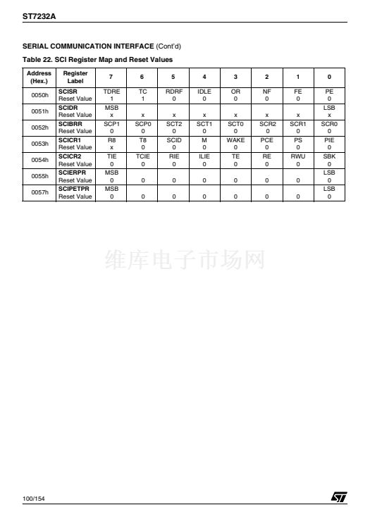
ST7232A
CENTRAL PROCESSING UNIT
(Cont鈥檇)
Stack Pointer (SP)
Read/Write
Reset Value: 01 FFh
15
0
7
SP7
SP6
SP5
SP4
SP3
SP2
SP1
8
0
0
0
0
0
0
1
0
SP0
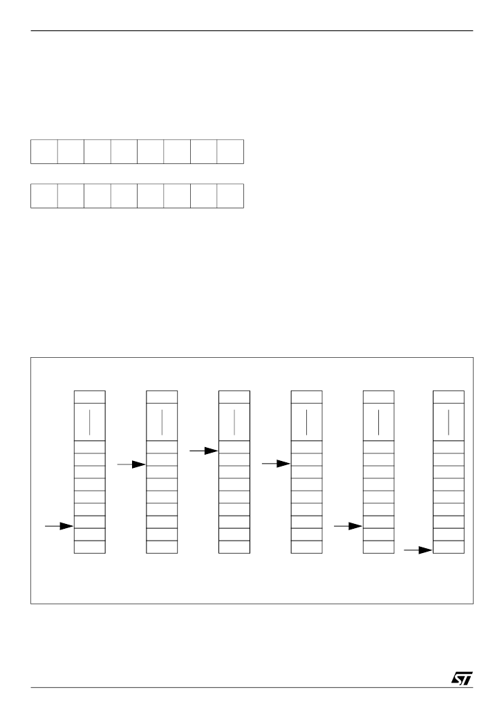
The Stack Pointer is a 16-bit register which is al-
ways pointing to the next free location in the stack.
It is then decremented after data has been pushed
onto the stack and incremented before data is
popped from the stack (see
Figure 8).
Since the stack is 256 bytes deep, the 8 most sig-
nificant bits are forced by hardware. Following an
MCU Reset, or after a Reset Stack Pointer instruc-
tion (RSP), the Stack Pointer contains its reset val-
ue (the SP7 to SP0 bits are set) which is the stack
higher address.
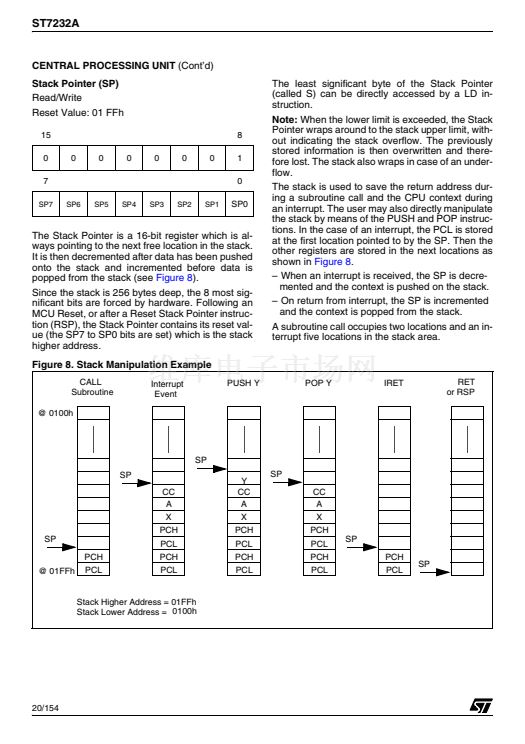
Figure 8. Stack Manipulation Example
CALL
Subroutine
@ 0100h
Interrupt
Event
PUSH Y
The least significant byte of the Stack Pointer
(called S) can be directly accessed by a LD in-
struction.
Note:
When the lower limit is exceeded, the Stack
Pointer wraps around to the stack upper limit, with-
out indicating the stack overflow. The previously
stored information is then overwritten and there-
fore lost. The stack also wraps in case of an under-
flow.
The stack is used to save the return address dur-
ing a subroutine call and the CPU context during
an interrupt. The user may also directly manipulate
the stack by means of the PUSH and POP instruc-
tions. In the case of an interrupt, the PCL is stored
at the first location pointed to by the SP. Then the
other registers are stored in the next locations as
shown in
Figure 8.
鈥?When an interrupt is received, the SP is decre-
mented and the context is pushed on the stack.
鈥?On return from interrupt, the SP is incremented
and the context is popped from the stack.
A subroutine call occupies two locations and an in-
terrupt five locations in the stack area.
POP Y
IRET
RET
or RSP
SP
SP
CC
A
X
PCH
SP
PCH
@ 01FFh
PCL
PCL
PCH
PCL
Y
CC
A
X
PCH
PCL
PCH
PCL
SP
CC
A
X
PCH
PCL
PCH
PCL
SP
PCH
PCL
SP
Stack Higher Address = 01FFh
Stack Lower Address = 0100h
20/154
1


 1
1
 2
2
 3
3
 4
4
 5
5
 6
6
 7
7
 8
8
 9
9
 10
10
 11
11
 12
12
 13
13
 14
14
 15
15
 16
16
 17
17
 18
18
 19
19
 20
20
 21
21
 22
22
 23
23
 24
24
 25
25
 26
26
 27
27
 28
28
 29
29
 30
30
 31
31
 32
32
 33
33
 34
34
 35
35
 36
36
 37
37
 38
38
 39
39
 40
40
 41
41
 42
42
 43
43
 44
44
 45
45
 46
46
 47
47
 48
48
 49
49
 50
50
 51
51
 52
52
 53
53
 54
54
 55
55
 56
56
 57
57
 58
58
 59
59
 60
60
 61
61
 62
62
 63
63
 64
64
 65
65
 66
66
 67
67
 68
68
 69
69
 70
70
 71
71
 72
72
 73
73
 74
74
 75
75
 76
76
 77
77
 78
78
 79
79
 80
80
 81
81
 82
82
 83
83
 84
84
 85
85
 86
86
 87
87
 88
88
 89
89
 90
90
 91
91
 92
92
 93
93
 94
94
 95
95
 96
96
 97
97
 98
98
 99
99
 100
100
 101
101
 102
102
 103
103
 104
104
 105
105
 106
106
 107
107
 108
108
 109
109
 110
110
 111
111
 112
112
 113
113
 114
114
 115
115
 116
116
 117
117
 118
118
 119
119
 120
120
 121
121
 122
122
 123
123
 124
124
 125
125
 126
126
 127
127
 128
128
 129
129
 130
130
 131
131
 132
132
 133
133
 134
134
 135
135
 136
136
 137
137
 138
138
 139
139
 140
140
 141
141
 142
142
 143
143
 144
144
 145
145
 146
146
 147
147
 148
148
 149
149
 150
150
 151
151
 152
152
 153
153
 154
154
