ST7232A
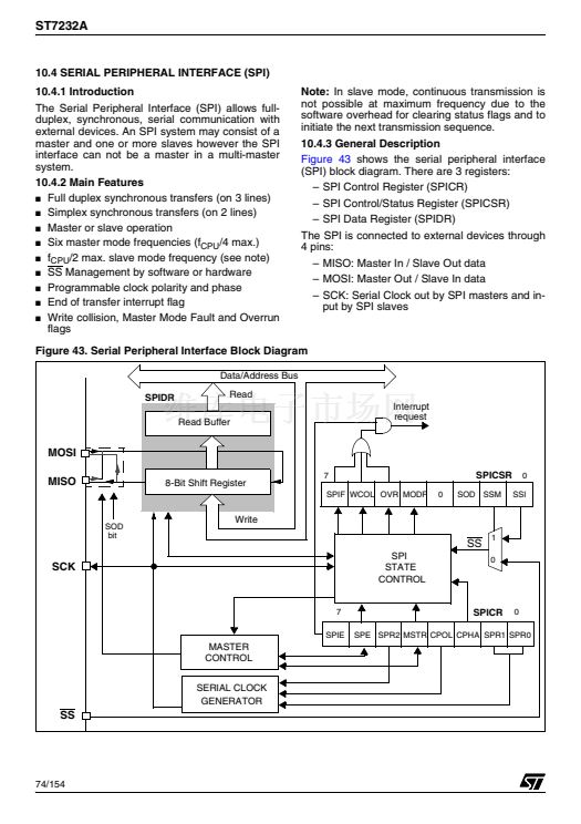
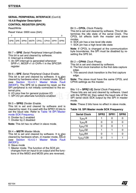
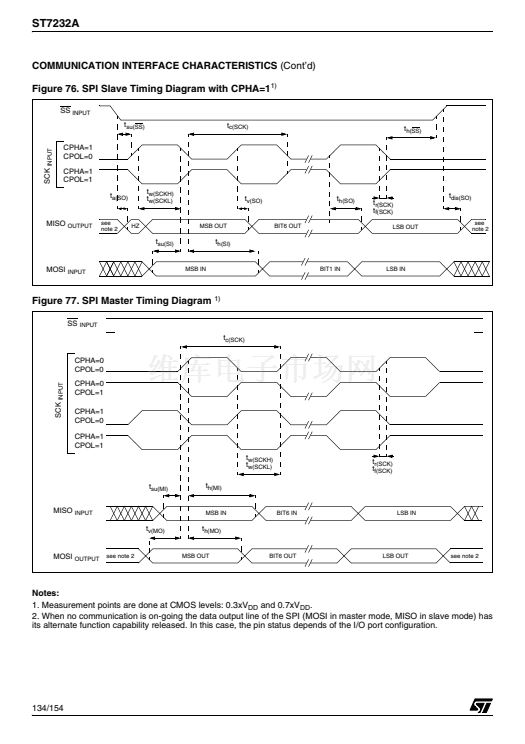
SERIAL PERIPHERAL INTERFACE
(Cont鈥檇)
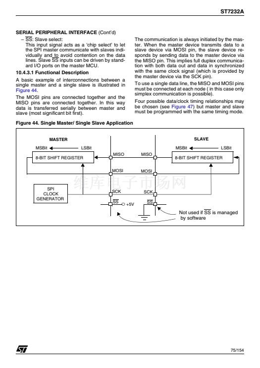
10.4.3.2 Slave Select Management
As an alternative to using the SS pin to control the
Slave Select signal, the application can choose to
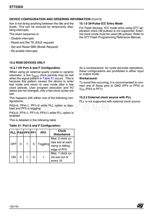
manage the Slave Select signal by software. This
is configured by the SSM bit in the SPICSR regis-
ter (see
Figure 46)
In software management, the external SS pin is
free for other application uses and the internal SS
signal level is driven by writing to the SSI bit in the
SPICSR register.
In Master mode:
鈥?SS internal must be held high continuously
In Slave Mode:
There are two cases depending on the data/clock
timing relationship (see
Figure 45):
If CPHA=1 (data latched on 2nd clock edge):
鈥?SS internal must be held low during the entire
transmission. This implies that in single slave
applications the SS pin either can be tied to
V
SS
, or made free for standard I/O by manag-
ing the SS function by software (SSM= 1 and
SSI=0 in the in the SPICSR register)
If CPHA=0 (data latched on 1st clock edge):
鈥?SS internal must be held low during byte
transmission and pulled high between each
byte to allow the slave to write to the shift reg-
ister. If SS is not pulled high, a Write Collision
error will occur when the slave writes to the
shift register (see
Section 10.4.5.3).
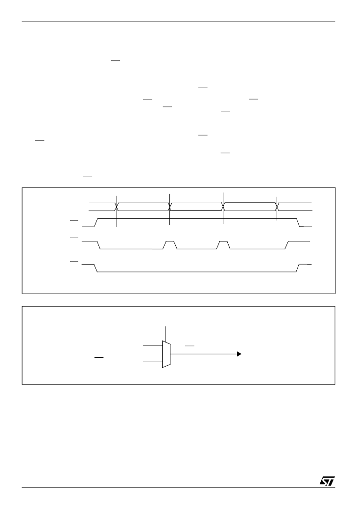
Figure 45. Generic SS Timing Diagram
MOSI/MISO
Master SS
Slave SS
(if CPHA=0)
Slave SS
(if CPHA=1)
Byte 1
Byte 2
Byte 3
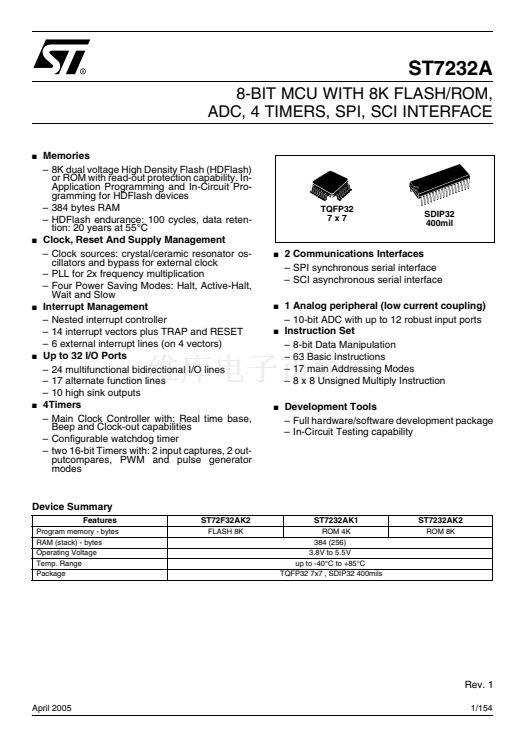
Figure 46. Hardware/Software Slave Select Management
SSM bit
SSI bit
SS external pin
1
0
SS internal
76/154
1


 1
1
 2
2
 3
3
 4
4
 5
5
 6
6
 7
7
 8
8
 9
9
 10
10
 11
11
 12
12
 13
13
 14
14
 15
15
 16
16
 17
17
 18
18
 19
19
 20
20
 21
21
 22
22
 23
23
 24
24
 25
25
 26
26
 27
27
 28
28
 29
29
 30
30
 31
31
 32
32
 33
33
 34
34
 35
35
 36
36
 37
37
 38
38
 39
39
 40
40
 41
41
 42
42
 43
43
 44
44
 45
45
 46
46
 47
47
 48
48
 49
49
 50
50
 51
51
 52
52
 53
53
 54
54
 55
55
 56
56
 57
57
 58
58
 59
59
 60
60
 61
61
 62
62
 63
63
 64
64
 65
65
 66
66
 67
67
 68
68
 69
69
 70
70
 71
71
 72
72
 73
73
 74
74
 75
75
 76
76
 77
77
 78
78
 79
79
 80
80
 81
81
 82
82
 83
83
 84
84
 85
85
 86
86
 87
87
 88
88
 89
89
 90
90
 91
91
 92
92
 93
93
 94
94
 95
95
 96
96
 97
97
 98
98
 99
99
 100
100
 101
101
 102
102
 103
103
 104
104
 105
105
 106
106
 107
107
 108
108
 109
109
 110
110
 111
111
 112
112
 113
113
 114
114
 115
115
 116
116
 117
117
 118
118
 119
119
 120
120
 121
121
 122
122
 123
123
 124
124
 125
125
 126
126
 127
127
 128
128
 129
129
 130
130
 131
131
 132
132
 133
133
 134
134
 135
135
 136
136
 137
137
 138
138
 139
139
 140
140
 141
141
 142
142
 143
143
 144
144
 145
145
 146
146
 147
147
 148
148
 149
149
 150
150
 151
151
 152
152
 153
153
 154
154
