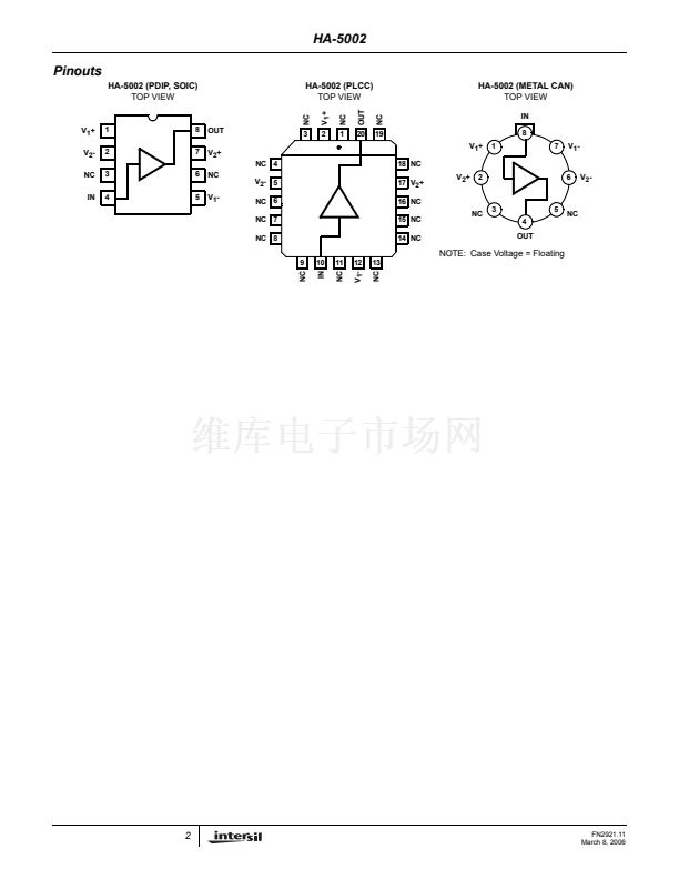
HA-5002
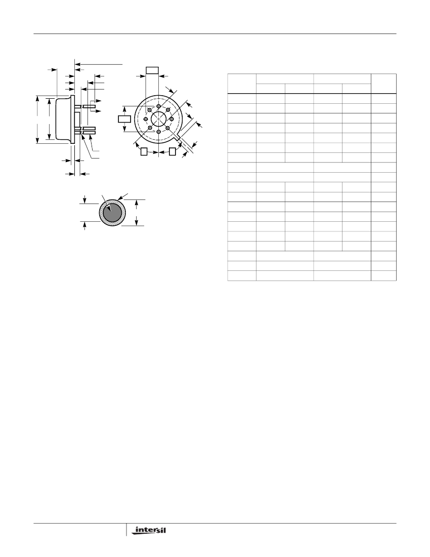
Metal Can Packages (Can)
REFERENCE PLANE
A
L
L2
L1
A
A
脴D 脴D1
脴
e
2
1
脴b1
F
Q
脴b
BASE AND
SEATING PLANE
BASE METAL
LEAD FINISH
尾
N
k1
脴D2
T8.C
MIL-STD-1835 MACY1-X8 (A1)
e
1
8 LEAD METAL CAN PACKAGE
INCHES
SYMBOL
A
脴b
脴b1
脴b2
脴D
MIN
0.165
0.016
0.016
0.016
0.335
0.305
0.110
MAX
0.185
0.019
0.021
0.024
0.375
0.335
0.160
MILLIMETERS
MIN
4.19
0.41
0.41
0.41
8.51
7.75
2.79
MAX
4.70
0.48
0.53
0.61
9.40
8.51
4.06
NOTES
-
1
1
-
-
-
-
-
-
-
-
2
1
1
1
-
3
3
4
Rev. 0 5/18/94
伪
k
脴D1
C
L
脴D2
e
e1
F
k
k1
0.200 BSC
0.100 BSC
-
0.027
0.027
0.500
-
0.250
0.010
45
o
BSC
45
o
BSC
8
0.040
0.034
0.045
0.750
0.050
-
0.045
-
5.08 BSC
2.54 BSC
1.02
0.86
1.14
19.05
1.27
-
1.14
0.69
0.69
12.70
-
6.35
0.25
脴b1
脴b2
L
L1
SECTION A-A
L2
Q
NOTES:
1. (All leads) 脴b applies between L1 and L2. 脴b1 applies between
L2 and 0.500 from the reference plane. Diameter is uncontrolled
in L1 and beyond 0.500 from the reference plane.
2. Measured from maximum diameter of the product.
3.
伪
is the basic spacing from the centerline of the tab to terminal 1
and
尾
is the basic spacing of each lead or lead position (N -1
places) from
伪
,
looking at the bottom of the package.
4. N is the maximum number of terminal positions.
5. Dimensioning and tolerancing per ANSI Y14.5M - 1982.
6. Controlling dimension: INCH.
伪
尾
N
45
o
BSC
45
o
BSC
8
12
FN2921.11
March 8, 2006


 1
1
 2
2
 3
3
 4
4
 5
5
 6
6
 7
7
 8
8
 9
9
 10
10
 11
11
 12
12
 13
13
 14
14
