= 500鈩?/div>
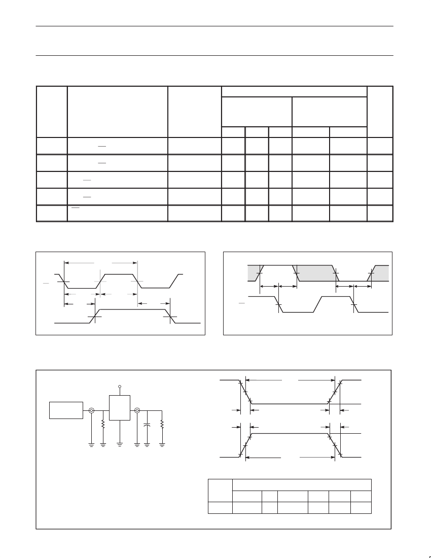
MIN
2.0
2.0
1.0
1.0
7.0
6.0
0
0
5.0
7.0
MAX
ns
ns
ns
ns
ns
SYMBOL
PARAMETER
UNIT
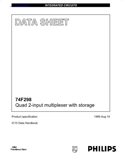
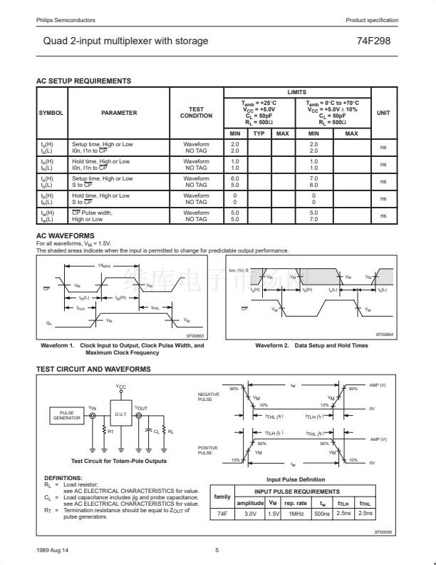
AC WAVEFORMS
For all waveforms, V
M
= 1.5V.
The shaded areas indicate when the input is permitted to change for predictable output performance.
1/f
MAX
Ion, I1n, S
V
M
CP
V
M
t
W
(L)
t
PLH
Q
n
V
M
t
W
(H)
t
PHL
V
M
CP
V
M
V
M
V
M
t
s
(H)
V
M
t
h
(H)
t
s
(L)
V
M
V
M
t
h
(L)
SF00863
SF00864
Waveform 1. Clock Input to Output, Clock Pulse Width, and
Maximum Clock Frequency
Waveform 2. Data Setup and Hold Times
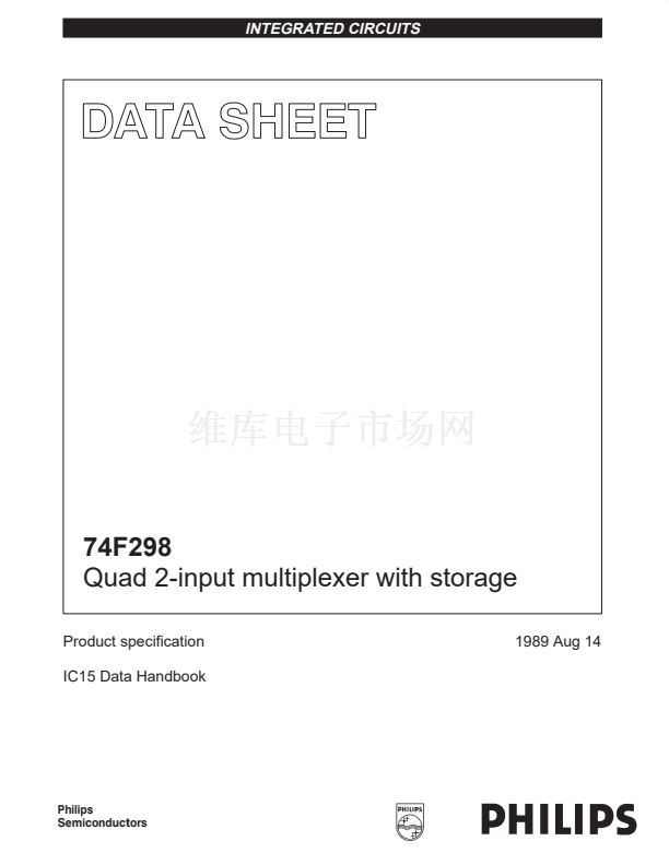
TEST CIRCUIT AND WAVEFORMS
V
CC
NEGATIVE
PULSE
V
IN
PULSE
GENERATOR
R
T
D.U.T.
V
OUT
90%
V
M
10%
t
THL (
t
f
)
C
L
R
L
t
w
V
M
10%
t
TLH (
t
r
)
0V
90%
AMP (V)
t
TLH (
t
r
)
90%
POSITIVE
PULSE
V
M
10%
t
w
t
THL (
t
f
)
AMP (V)
90%
V
M
10%
0V
Test Circuit for Totem-Pole Outputs
DEFINITIONS:
R
L
= Load resistor;
see AC ELECTRICAL CHARACTERISTICS for value.
C
L
= Load capacitance includes jig and probe capacitance;
see AC ELECTRICAL CHARACTERISTICS for value.
R
T
= Termination resistance should be equal to Z
OUT
of
pulse generators.
Input Pulse Definition
INPUT PULSE REQUIREMENTS
family
amplitude V
M
74F
3.0V
1.5V
rep. rate
1MHz
t
w
500ns
t
TLH
2.5ns
t
THL
2.5ns
SF00006
1989 Aug 14
5


 1
1
 2
2
 3
3
 4
4
 5
5
 6
6
 7
7
 8
8
