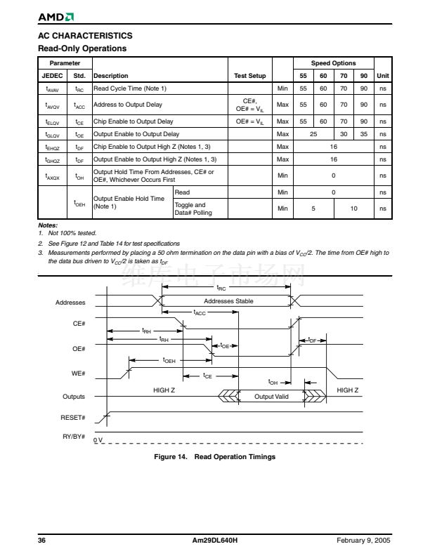
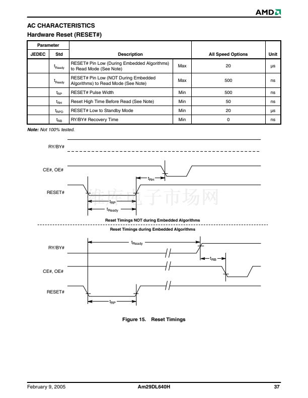
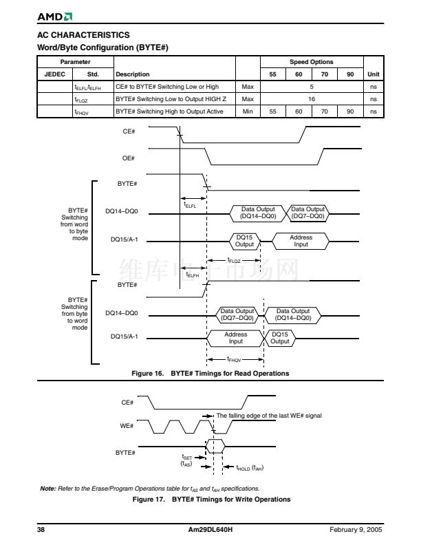
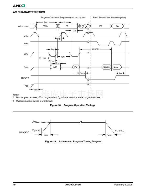
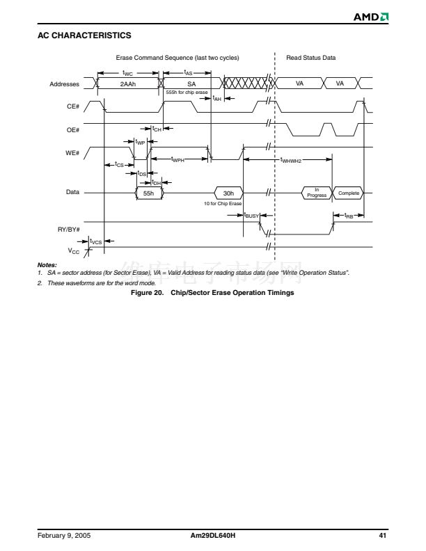
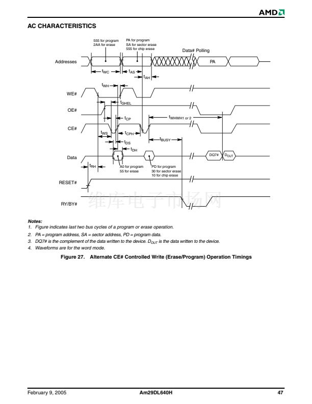
AC CHARACTERISTICS
Read-Only Operations
Parameter
JEDEC
t
AVAV
t
AVQV
t
ELQV
t
GLQV
t
EHQZ
t
GHQZ
t
AXQX
Std.
t
RC
t
ACC
t
CE
t
OE
t
DF
t
DF
t
OH
Description
Read Cycle Time (Note 1)
Address to Output Delay
Chip Enable to Output Delay
Output Enable to Output Delay
Chip Enable to Output High Z (Notes 1, 3)
Output Enable to Output High Z (Notes 1, 3)
Output Hold Time From Addresses, CE# or
OE#, Whichever Occurs First
Read
t
OEH
Output Enable Hold Time
(Note 1)
Toggle and
Data# Polling
CE#,
OE# = V
IL
OE# = V
IL
Test Setup
Min
Max
Max
Max
Max
Max
Min
Min
Min
5
55
55
55
55
25
16
16
0
0
10
Speed Options
60
60
60
60
70
70
70
70
30
90
90
90
90
35
Unit
ns
ns
ns
ns
ns
ns
ns
ns
ns
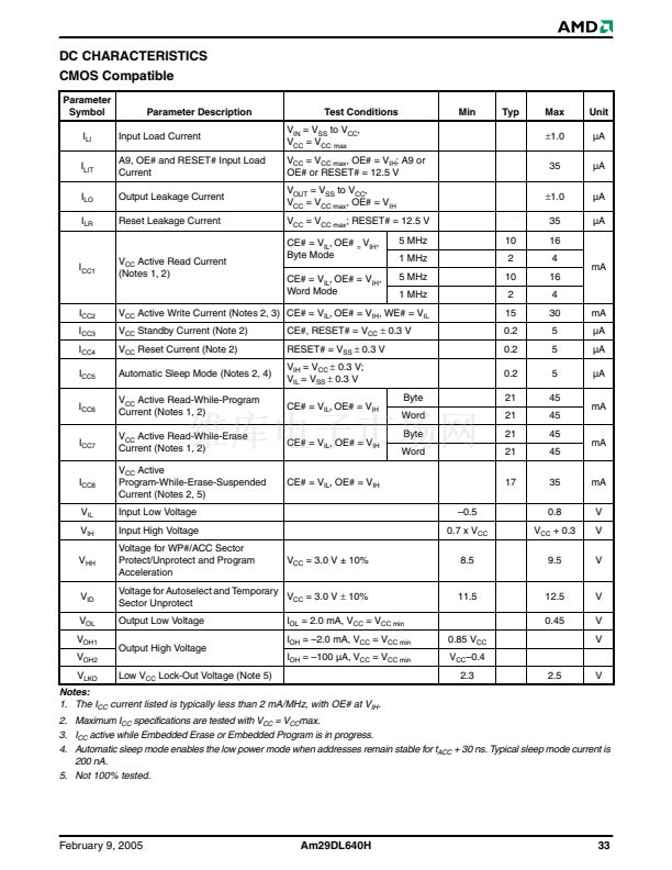
Notes:
1. Not 100% tested.
2. See Figure 12 and Table 14 for test specifications
3. Measurements performed by placing a 50 ohm termination on the data pin with a bias of V
CC
/2. The time from OE# high to
the data bus driven to V
CC
/2 is taken as t
DF
.
t
RC
Addresses
CE#
t
RH
t
RH
OE#
t
OEH
WE#
HIGH Z
Outputs
RESET#
RY/BY#
Output Valid
t
CE
t
OH
HIGH Z
t
OE
t
DF
Addresses Stable
t
ACC
0V
Figure 14.
Read Operation Timings
36
Am29DL640H
February 9, 2005


 1
1
 2
2
 3
3
 4
4
 5
5
 6
6
 7
7
 8
8
 9
9
 10
10
 11
11
 12
12
 13
13
 14
14
 15
15
 16
16
 17
17
 18
18
 19
19
 20
20
 21
21
 22
22
 23
23
 24
24
 25
25
 26
26
 27
27
 28
28
 29
29
 30
30
 31
31
 32
32
 33
33
 34
34
 35
35
 36
36
 37
37
 38
38
 39
39
 40
40
 41
41
 42
42
 43
43
 44
44
 45
45
 46
46
 47
47
 48
48
 49
49
 50
50
 51
51
 52
52
 53
53
 54
54
