DC鈥?/div>
GND
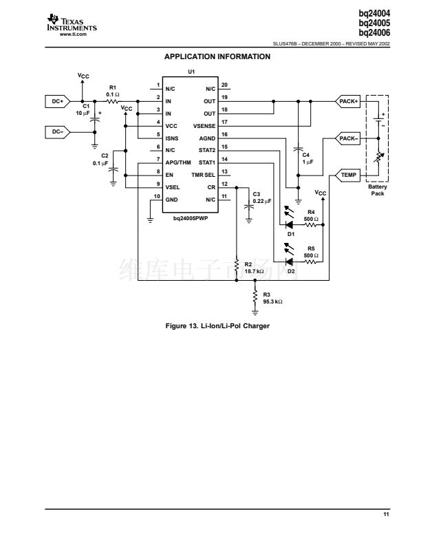
bq24005PWP
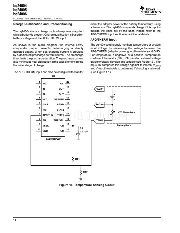
Figure 17. Temperature Threshold
Figure 18. APG Sensing Circuit
Values of resistors R1 and R2 can be calculated using the following equation:
R2
V
(APG)
+
V
CC
(R1
)
R2)
where V
(APG)
is the voltage at the APG/THM pin.
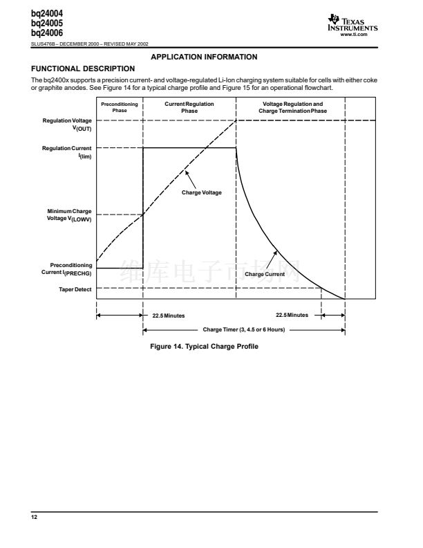
Current Regulation
The bq2400x provides current regulation while the battery-pack voltage is less than the regulation voltage. The current
regulation loop effectively amplifies the error between a reference signal, Vilim, and the drop across the external sense
resistor, R
SNS
.
VCC
1
R(SNS)
DC+
C1
10
碌F
DC鈥?/div>
+
VCC
2
3
4
5
6
C2
0.1
碌F
7
8
9
10
N/C
IN
IN
VCC
ISNS
N/C
APG/THM
EN
VSEL
GND
U1
N/C
OUT
OUT
VSENSE
AGND
STAT2
STAT1
TMR SEL
CR
N/C
20
19
18
17
16
15
14
13
12
11
bq24005PWP
Figure 19. Current Sensing Circuit
15


 1
1
 2
2
 3
3
 4
4
 5
5
 6
6
 7
7
 8
8
 9
9
 10
10
 11
11
 12
12
 13
13
 14
14
 15
15
 16
16
 17
17
 18
18
 19
19
 20
20
 21
21
 22
22
