DM74LS393
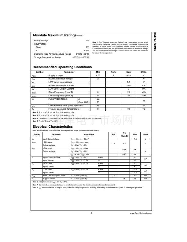
Absolute Maximum Ratings
(Note 1)
Supply Voltage
Input Voltage
Clear
A
Operating Free Air Temperature Range
Storage Temperature Range
7V
5.5V
0掳C to
+70掳C
鈭?5掳C
to
+150掳C
7V
Note 1:
The 鈥淎bsolute Maximum Ratings鈥?are those values beyond which
the safety of the device cannot be guaranteed. The device should not be
operated at these limits. The parametric values defined in the Electrical
Characteristics tables are not guaranteed at the absolute maximum ratings.
The 鈥淩ecommended Operating Conditions鈥?table will define the conditions
for actual device operation.
Recommended Operating Conditions
Symbol
V
CC
V
IH
V
IL
I
OH
I
OL
f
CLK
f
CLK
t
W
t
REL
T
A
Supply Voltage
HIGH Level Input Voltage
LOW Level Input Voltage
HIGH Level Output Current
LOW Level Output Current
Clock Frequency (Note 2)
Clock Frequency (Note 3)
Pulse Width (Note 5)
A
Clear HIGH
Clear Release Time (Note 4)(Note 5)
Free Air Operating Temperature
0
0
20
20
25鈫?/div>
0
70
Parameter
Min
4.75
2
0.8
鈭?.4
8
25
20
Nom
5
Max
5.25
Units
V
V
V
mA
mA
MHz
MHz
ns
ns
掳C
Note 2:
C
L
=
15 pF, R
L
=
2 k鈩? T
A
=
25掳C and V
CC
=
5V.
Note 3:
C
L
=
50 pF, R
L
=
2 k鈩? T
A
=
25掳C and V
CC
=
5V.
Note 4:
The symbol (鈫? indicates that the falling edge of the clear pulse is used for reference.
Note 5:
T
A
=
25掳C, and V
CC
=
5V.
Electrical Characteristics
over recommended operating free air temperature range (unless otherwise noted)
Symbol
V
I
V
OH
V
OL
Parameter
Input Clamp Voltage
HIGH Level
Output Voltage
LOW Level
Output Voltage
I
I
I
IH
I
IL
I
OS
I
CC
Input Current @ Max
Input Voltage
HIGH Level
Input Current
LOW Level
Input Current
Short Circuit Output Current
Supply Current
V
CC
=
Max (Note 7)
V
CC
=
Max (Note 8)
V
CC
=
Max, V
I
=
0.4V
Conditions
V
CC
=
Min, I
I
= 鈭?8
mA
V
CC
=
Min, I
OH
=
Max
V
IL
=
Max, V
IH
=
Min
V
CC
=
Min, I
OL
=
Max
V
IL
=
Max, V
IH
=
Min
I
OL
=
4 mA, V
CC
=
Min
V
CC
=
Max, V
I
=
7V
V
CC
=
Max, V
I
=
5.5V
V
CC
=
Max, V
I
=
2.7V
Clear
A
Clear
A
Clear
A
鈭?0
15
2.7
3.4
0.35
0.25
0.5
0.4
0.1
0.2
20
40
鈭?.4
鈭?.6
鈭?00
26
mA
碌A
mA
mA
mA
Min
Typ
(Note 6)
Max
鈭?.5
Units
V
V
V
Note 6:
All typicals are at V
CC
=
5V, T
A
=
25掳C.
Note 7:
Not more than one output should be shorted at a time, and the duration should not exceed one second.
Note 8:
I
CC
is measured with all outputs open, both CLEAR inputs grounded following momentary connection to 4.5V, and all other inputs grounded.
3
www.fairchildsemi.com


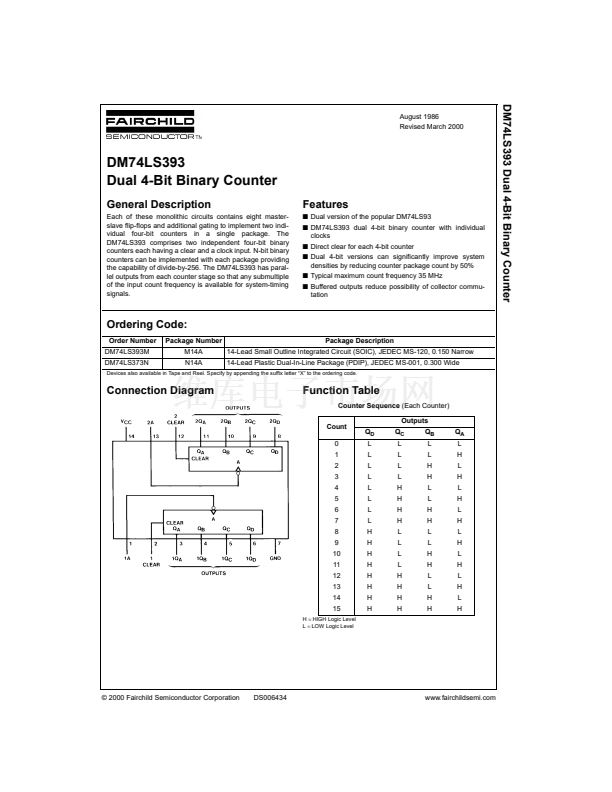 1
1
 2
2
 3
3
 4
4
 5
5
 6
6
