HT600/680/6207
Address/data programming (preset)
The status of each address/data pin can be individually preset to logic
虏high虏, 虏low虏,
or
虏floating虏.
If a
transmission enable signal is applied, the encoder scans and transmits the status of the 18 bits of ad-
dress/data serially in the order A0 to AD17 for the HT600/HT680 and A0 to D15 for the HT6207.
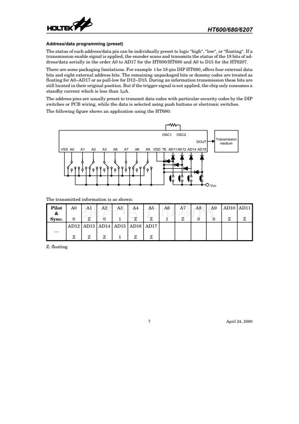
There are some packaging limitations. For example t he 18-pin DIP HT680, offers four external data
bits and eight external address bits. The remaining unpackaged bits or dummy codes are treated as
floating for A0~AD17 or as pull-low for D12~D15. During an information transmission these bits are
still located in their original position. But if the trigger signal is not applied, the chip only consumes a
standby current which is less than 1mA.
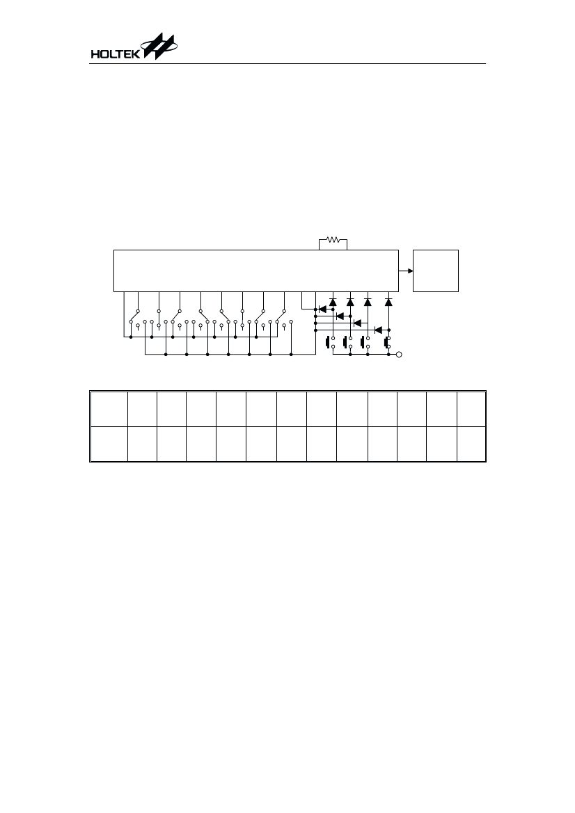
The address pins are usually preset to transmit data codes with particular security codes by the DIP
switches or PCB wiring, while the data is selected using push buttons or electronic switches.
The following figure shows an application using the HT680:
O S C 1
O S C 2
D O U T
T r a n s m is s io n
m e d iu m
V S S
A 0
A 1
A 2
A 3
A 6
A 7
A 8
A 9
V D D
T E
A D 1 1 A D 1 2 A D 1 4 A D 1 5
V
D D
The transmitted information is as shown:
Pilot
&
Sync.
戮
Z: floating
A0
0
A1
Z
A2
0
A3
1
A4
Z
A5
Z
A6
1
A7
Z
A8
0
A9
0
AD10 AD11
Z
Z
AD12 AD13 AD14 AD15 AD16 AD17
Z
Z
Z
1
Z
Z
7
April 24, 2000


 1
1
 2
2
 3
3
 4
4
 5
5
 6
6
 7
7
 8
8
 9
9
 10
10
 11
11
