ISL6224
Absolute Maximum Ratings
Bias Voltage, V
CC
. . . . . . . . . . . . . . . . . . . . . . . . . . . . . . -0.3V to +7V
Input Voltage, Vin . . . . . . . . . . . . . . . . . . . . . . . . . . . . . . . . . . +27.0V
Phase and Isen Pins . . . . . . . . . . . . . . . . . . . . . GND -0.3V to +29.0V
BOOT and Ugate Pins . . . . . . . . . . . . . . . . . . . . . . . . . . . . . . . . + 32.0V
BOOT with respect to PHASE . . . . . . . . . . . . . . . . . . . . . . . . . .+ 7.0V
All other pins . . . . . . . . . . . . . . . . . . . . . . . . . . . . GND -0.3V to 15V
ESD Classification . . . . . . . . . . . . . . . . . . . . . . . . . . . . . . . . . Class 2
Thermal Information
Thermal Resistance (Typical, Note 1)
胃
JA
(掳C/W)
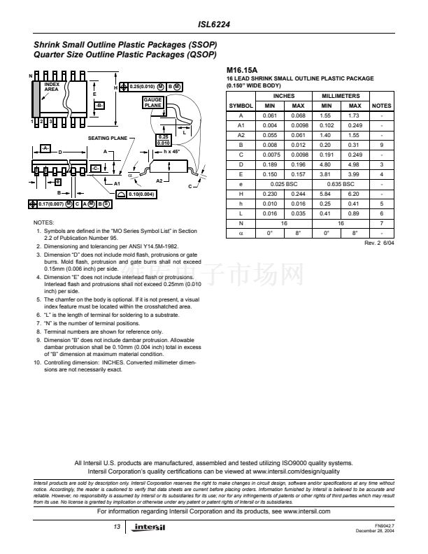
SSOP Package . . . . . . . . . . . . . . . . . . . . . . . . . . . .
112
Maximum Junction Temperature (Plastic Package) . . . . . . . . 150掳C
Maximum Storage Temperature Range . . . . . . . . . . . -65掳C to 150掳C
Maximum Lead Temperature (Soldering 10s) . . . . . . . . . . . . . 300掳C
(SSOP - Lead Tips Only)
Recommended Operating Conditions
Bias Voltage, V
CC
. . . . . . . . . . . . . . . . . . . . . . . . . . . . . . . +5.0V 卤5%
Input Voltage, Vin . . . . . . . . . . . . . . . . . . . . . . . . . . . . 4.0V to +24.0V
Ambient Temperature Range . . . . . . . . . . . . . . . . . . . .-10掳C to 85掳C
Junction Temperature Range. . . . . . . . . . . . . . . . . . .-10掳C to 125掳C
CAUTION: Stresses above those listed in 鈥淎bsolute Maximum Ratings鈥?may cause permanent damage to the device. This is a stress only rating and operation of the
device at these or any other conditions above those indicated in the operational sections of this specification is not implied.
NOTE:
3.
胃
JA
is measured with the component mounted on a high effective thermal conductivity test board in free air. See Tech Brief TB379 for details.
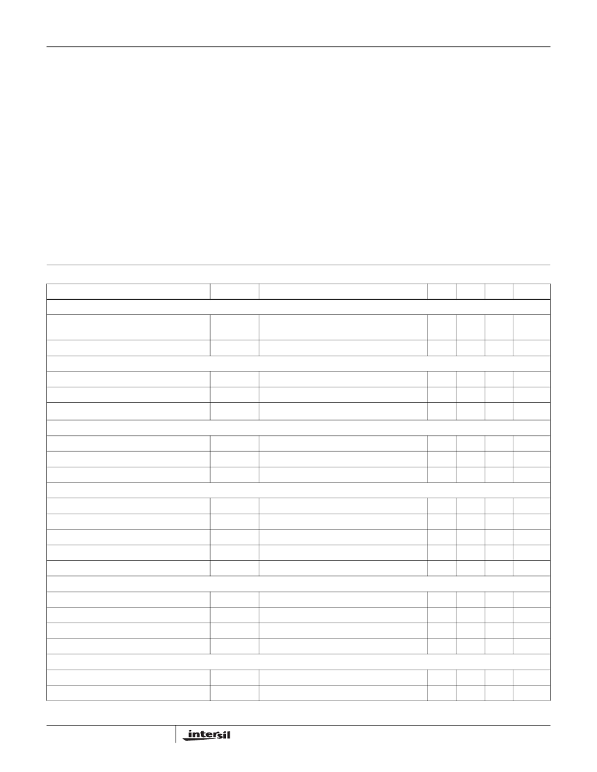
Electrical Specifications
PARAMETER
VCC SUPPLY
Bias Current
Shutdown Current
VCC UVLO
Rising Vcc Threshold
Falling Vcc Threshold
Vcc UVLO Hysteris
VIN
Input Voltage Pin Current (Sink)
Input Voltage Pin Current (Source)
Shutdown Current
OSCILLATOR
PWM Oscillator Frequency
PWM Oscillator Frequency
Ramp Amplitude, pk-pk
Ramp Amplitude, pk-pk
Ramp Offset
REFERENCE AND SOFT-START
Internal Reference Voltage
Reference Voltage Accuracy
Soft-Start Current During Start-up
Soft-Start Threshold
PWM CONVERTER
Load Regulation
VSEN pin bias current
Operating Conditions: V
CC
= 5V, T
A
= 10掳C to 85掳C, Unless Otherwise Noted.
SYMBOL
TEST CONDITIONS
MIN
TYP
MAX
UNITS
I
CC
I
CCSN
LGATE, UGATE Open, VSEN forced above
regulation point
-
-
850
5
1300
15
碌A
碌A
4.3
4.1
0.1
-
-
-
4.75
4.5
0.5
V
V
V
I
VIN
I
VIN
I
VIN
VIN pin connected to the input voltage source
VIN pin connected to ground
10
-7
-
20
-15
-
30
-20
1
碌A
碌A
碌A
F
c1
F
c2
V
R1
V
R2
V
ROFF
V
IN
= 3.5V - 24V
V
IN
鈮?/div>
0.5V
V
IN
= 16V, By Design
V
IN
鈮?/div>
5V, By Design
255
510
-
-
-
300
600
2
1.25
0.5
345
690
-
-
-
kHz
kHz
V
V
V
V
REF
-
-1.0
0.9
-
5
1.5
-
+1.0
-
-
V
%
碌A
V
I
SOFT
V
SOFT
-
-
0.0mA < I
VOUT1
< 3.0A; 5.0V < V
IN
< 24.0V
I
VSEN
-1.0
-
-
80
+1.0
-
%
nA
2
FN9042.7
December 28, 2004


 1
1
 2
2
 3
3
 4
4
 5
5
 6
6
 7
7
 8
8
 9
9
 10
10
 11
11
 12
12
 13
13
