LT1991
APPLICATIO S I FOR ATIO
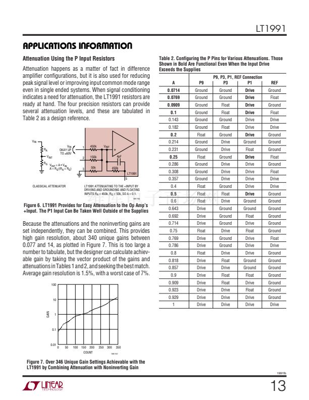
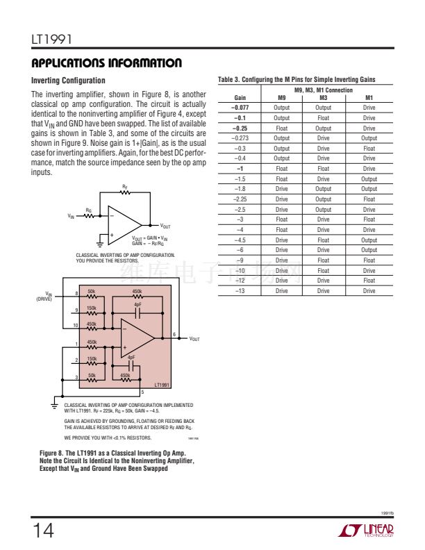
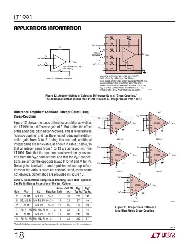
Inverting Configuration
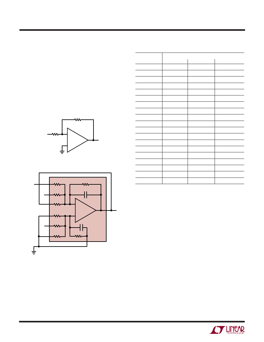
The inverting amplifier, shown in Figure 8, is another
classical op amp configuration. The circuit is actually
identical to the noninverting amplifier of Figure 4, except
that V
IN
and GND have been swapped. The list of available
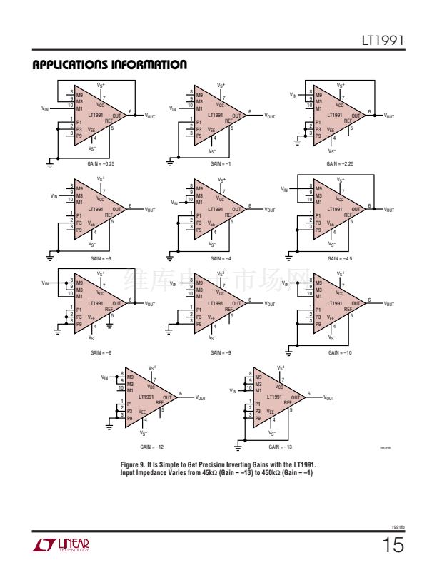
gains is shown in Table 3, and some of the circuits are
shown in Figure 9. Noise gain is 1+|Gain|, as is the usual
case for inverting amplifiers. Again, for the best DC perfor-
mance, match the source impedance seen by the op amp
inputs.
R
F
R
G
V
IN
鈥?/div>
V
OUT
+
V
OUT
= GAIN 鈥?V
IN
GAIN = 鈥?R
F
/R
G
CLASSICAL INVERTING OP AMP CONFIGURATION.
YOU PROVIDE THE RESISTORS.
V
IN
(DRIVE)
8
50k
450k
4pF
9
10
150k
450k
鈥?/div>
6
V
OUT
1
2
450k
150k
50k
+
4pF
3
450k
LT1991
5
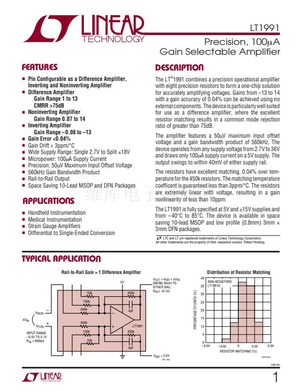
CLASSICAL INVERTING OP AMP CONFIGURATION IMPLEMENTED
WITH LT1991. R
F
= 225k, R
G
= 50k, GAIN = 鈥?.5.
GAIN IS ACHIEVED BY GROUNDING, FLOATING OR FEEDING BACK
THE AVAILABLE RESISTORS TO ARRIVE AT DESIRED R
F
AND R
G
.
WE PROVIDE YOU WITH <0.1% RESISTORS.
1991 F08
Figure 8. The LT1991 as a Classical Inverting Op Amp.
Note the Circuit Is Identical to the Noninverting Amplifier,
Except that V
IN
and Ground Have Been Swapped
14
U
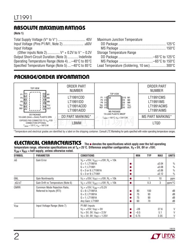
Table 3. Configuring the M Pins for Simple Inverting Gains
Gain
鈥?.077
鈥?.1
鈥?.25
鈥?.273
鈥?.3
鈥?.4
鈥?
鈥?.5
鈥?.8
鈥?.25
鈥?.5
鈥?
鈥?
鈥?.5
鈥?
鈥?
鈥?0
鈥?2
鈥?3
M9
Output
Output
Float
Output
Output
Output
Float
Float
Drive
Drive
Drive
Float
Float
Drive
Drive
Drive
Drive
Drive
Drive
M9, M3, M1 Connection
M3
Output
Float
Output
Drive
Drive
Drive
Float
Drive
Output
Output
Output
Drive
Drive
Float
Drive
Float
Float
Drive
Drive
M1
Drive
Drive
Drive
Output
Float
Drive
Drive
Output
Output
Float
Drive
Float
Drive
Output
Output
Float
Drive
Float
Drive
1991fb
W
U U


 1
1
 2
2
 3
3
 4
4
 5
5
 6
6
 7
7
 8
8
 9
9
 10
10
 11
11
 12
12
 13
13
 14
14
 15
15
 16
16
 17
17
 18
18
 19
19
 20
20
 21
21
 22
22
 23
23
 24
24
