M45PE40
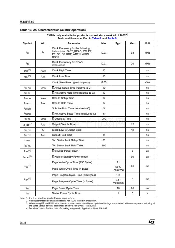
Table 13. AC Characteristics (33MHz operation)
33MHz only available for products marked since week 40 of 2005
(4)
Test conditions specified in
Table 8.
and
Table 9.
Symbol
Alt.
Parameter
Clock Frequency for the following
instructions: FAST_READ, PW, PP,
PE, SE, DP, RDP, WREN, WRDI,
RDSR
Clock Frequency for READ
instructions
t
CLH
t
CLL
Clock High Time
Clock Low Time
Clock Slew Rate
2
(peak to peak)
t
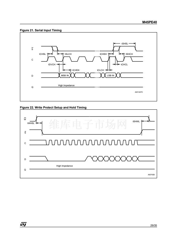
SLCH
t
CHSL
t
DVCH
t
CHDX
t
CHSH
t
SHCH
t
SHSL
t
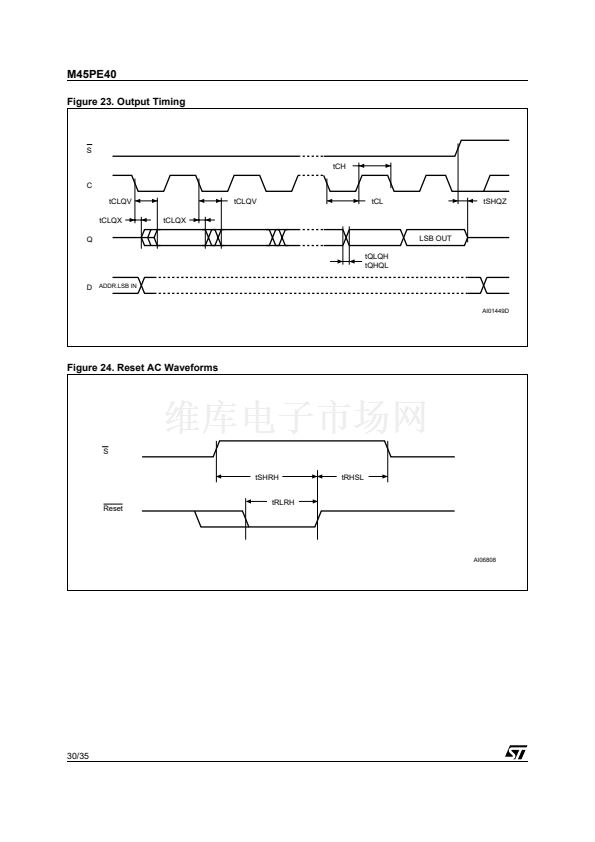
SHQZ (2)
t
CLQV
t
CLQX
t
THSL
t
SHTL
t
DP (2)
t
RDP (2)
(3)
Min.
Typ.
Max.
Unit
f
C
f
C
D.C.
33
MHz
f
R
t
CH (1)
t
CL (1)
D.C.
13
13
0.03
10
10
3
5
5
5
200
20
MHz
ns
ns
V/ns
ns
ns
ns
ns
ns
ns
ns
t
CSS
S Active Setup Time (relative to C)
S Not Active Hold Time (relative to C)
t
DSU
t
DH
Data In Setup Time
Data In Hold Time
S Active Hold Time (relative to C)
S Not Active Setup Time (relative to C)
t
CSH
t
DIS
t
V
t
HO
S Deselect Time
Output Disable Time
Clock Low to Output Valid
Output Hold Time
Top Sector Lock Setup Time
Top Sector Lock Hold Time
S to Deep Power-down
S High to Standby Power mode
Page Write Cycle Time (256 Bytes)
12
12
0
50
100
3
30
11
10.2+
n*0.8/256
1.2
0.4+
n*0.8/256
10
1
5
25
ns
ns
ns
ns
ns
碌s
碌s
t
PW
ms
Page Write Cycle Time (n Bytes)
Page Program Cycle Time (256 Bytes)
t
PP (3)
t
PE
t
SE
ms
Page Program Cycle Time (n Bytes)
Page Erase Cycle Time
Sector Erase Cycle Time
20
5
ms
s
Note: 1. t
CH
+ t
CL
must be greater than or equal to 1/ f
C
2. Value guaranteed by characterization, not 100% tested in production.
3. When using PP and PW instructions to update consecutive Bytes, optimized timings are obtained with one sequence including all
the Bytes versus several sequences of only a few Bytes. (1
鈮?/div>
n
鈮?/div>
256)
4. Details of how to find the date of marking are given in Application Note, AN1995.
28/35


 1
1
 2
2
 3
3
 4
4
 5
5
 6
6
 7
7
 8
8
 9
9
 10
10
 11
11
 12
12
 13
13
 14
14
 15
15
 16
16
 17
17
 18
18
 19
19
 20
20
 21
21
 22
22
 23
23
 24
24
 25
25
 26
26
 27
27
 28
28
 29
29
 30
30
 31
31
 32
32
 33
33
 34
34
 35
35
