-5V/-12V/-15V or Adjustable,
High-Efficiency, Low I
Q
DC-DC Inverters
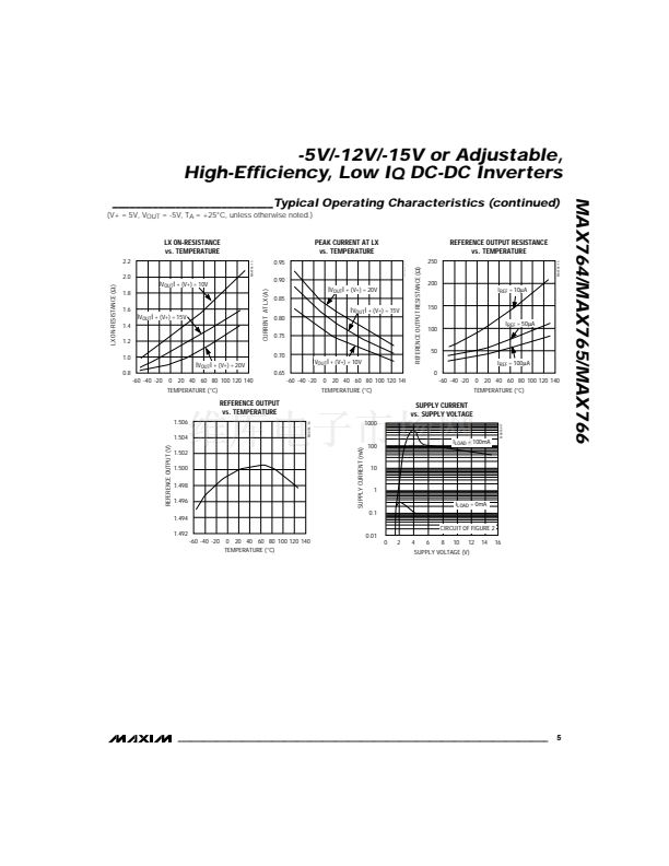
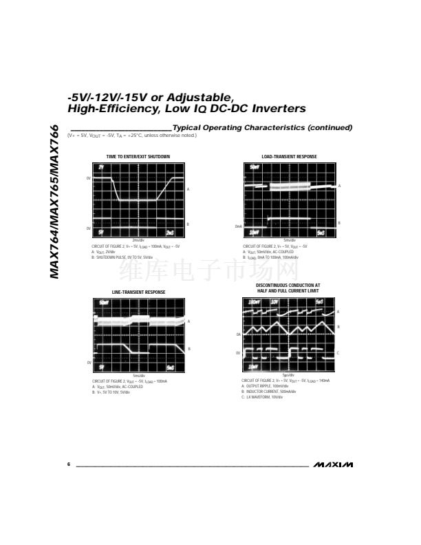
____________________________Typical Operating Characteristics (continued)
(V+ = 5V, V
OUT
= -5V, T
A
= +25掳C, unless otherwise noted.)
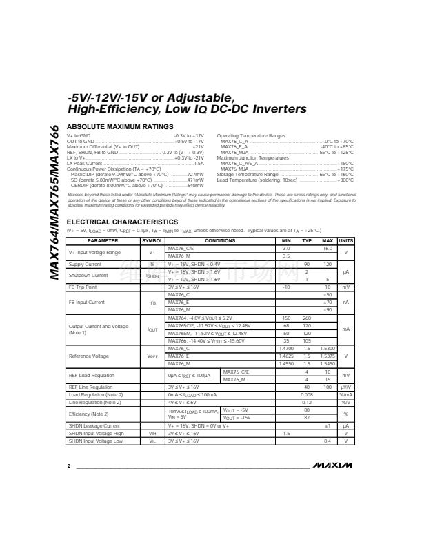
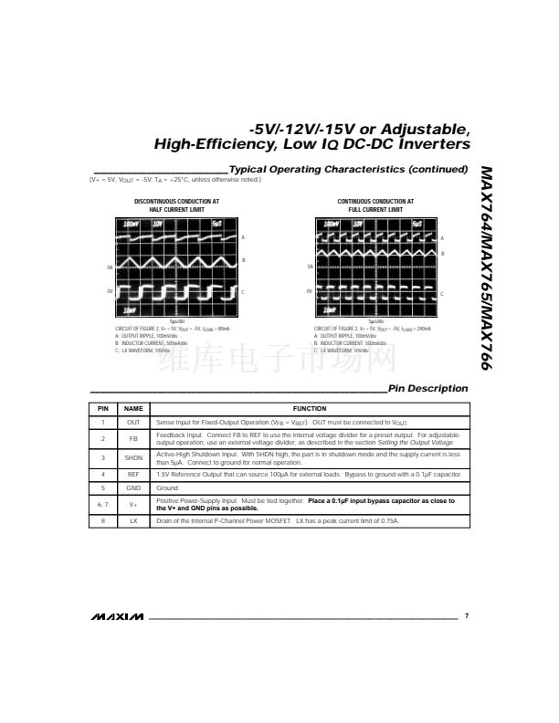
DISCONTINUOUS CONDUCTION AT
HALF CURRENT LIMIT
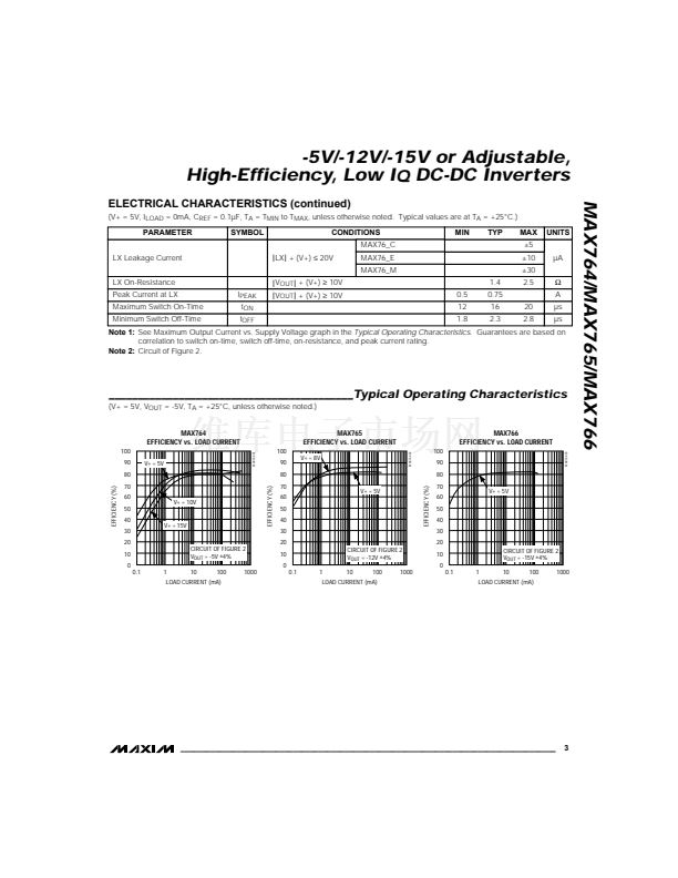
CONTINUOUS CONDUCTION AT
FULL CURRENT LIMIT
MAX764/MAX765/MAX766
A
A
B
B
0A
0A
0V
C
0V
C
5碌s/div
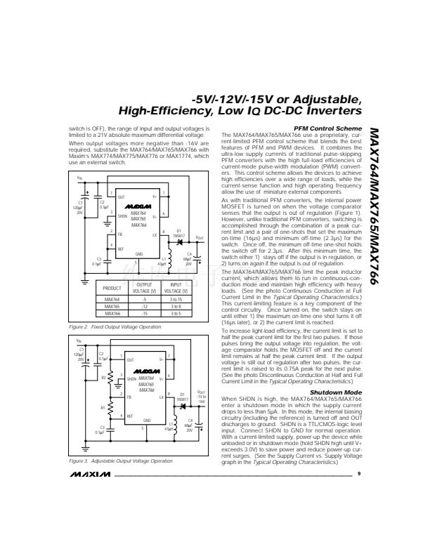
CIRCUIT OF FIGURE 2, V+ = 5V, V
OUT
= -5V, I
LOAD
= 80mA
A: OUTPUT RIPPLE, 100mV/div
B: INDUCTOR CURRENT, 500mA/div
C: LX WAVEFORM, 10V/div
5碌s/div
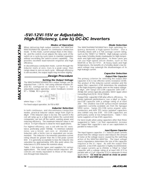
CIRCUIT OF FIGURE 2, V+ = 5V, V
OUT
= -5V, I
LOAD
= 240mA
A: OUTPUT RIPPLE, 100mV/div
B: INDUCTOR CURRENT, 500mA/div
C: LX WAVEFORM, 10V/div
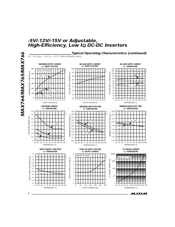
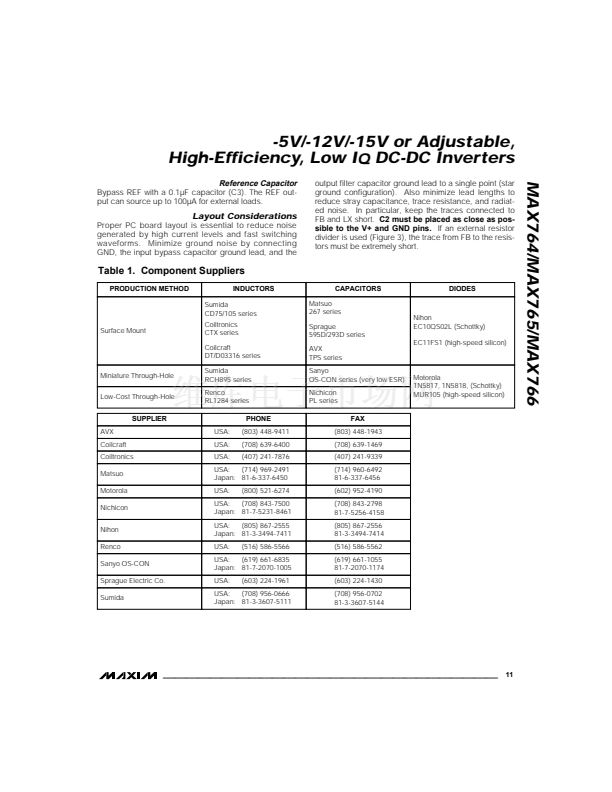
______________________________________________________________Pin Description
PIN
1
2
3
4
5
6, 7
8
NAME
OUT
FB
SHDN
REF
GND
V+
LX
FUNCTION
Sense Input for Fixed-Output Operation (V
FB
= V
REF
). OUT must be connected to V
OUT
.
Feedback Input. Connect FB to REF to use the internal voltage divider for a preset output. For adjustable-
output operation, use an external voltage divider, as described in the section
Setting the Output Voltage.
Active-High Shutdown Input. With SHDN high, the part is in shutdown mode and the supply current is less
than 5碌A. Connect to ground for normal operation.
1.5V Reference Output that can source 100碌A for external loads. Bypass to ground with a 0.1碌F capacitor.
Ground
Positive Power-Supply Input. Must be tied together.
Place a 0.1碌F input bypass capacitor as close to
the V+ and GND pins as possible.
Drain of the Internal P-Channel Power MOSFET. LX has a peak current limit of 0.75A.
_______________________________________________________________________________________
7


 1
1
 2
2
 3
3
 4
4
 5
5
 6
6
 7
7
 8
8
 9
9
 10
10
 11
11
 12
12
