MC3371 MC3372
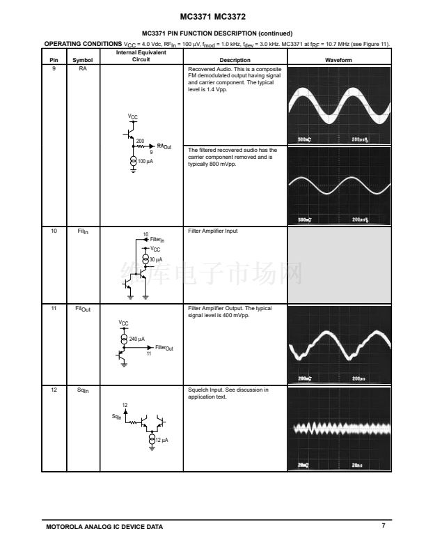
An external positive bias to Pin 12 sets up the squelch
trigger circuit such that the audio mute (Pin 14) is open or
connected to ground. If Pin 12 is pulled down to 0.9 V or
below by the noise or tone detector, Pin 14 is internally
shorted to ground. There is about 57 mV of hyteresis at
Pin 12 to prevent jitter. Audio muting is accomplished by
connecting Pin 14 to the appropriate point in the audio path
between Pin 9 and an audio amplifier. The voltage at Pin 14
should not be lower than 鈥?.7 V; this can be assured by
connecting Pin 14 to the point that has no dc component.
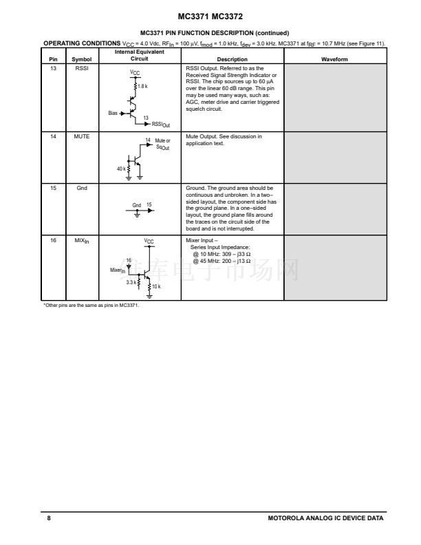
Another possible application of the squelch switch may
be as a carrier level triggered squelch circuit, similar to the
MC3362/MC3363 FM receivers. In this case the meter
output can be used directly to trigger the squelch switch
when the RF input at the input frequency falls below the
desired level. The level at which this occurs is determined
by the resistor placed between the meter drive output
(Pin 13) and ground (Pin 15).
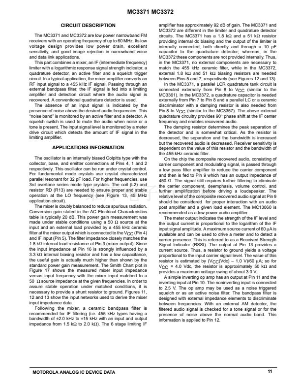
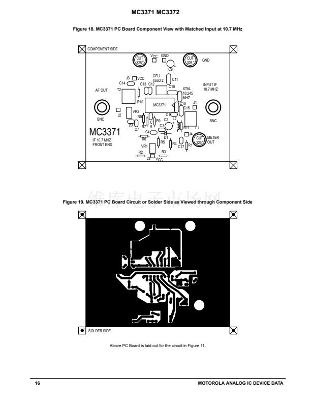
Figure 11. Typical Application for MC3371 at 10.7 MHz
VCC = 4.0 Vdc
RSSI Output
R2
10 k
1st IF 10.7 MHz
from Input
Front End
C2
4.7
碌F
L1
TKANS9443HM
6.8
碌H 卤6%
+
R3
100 k
R4
1.0 k
1N5817 R5
4.7 k R6
C3
0.1
C4
0.001
C5
0.001
R9
510 k
16
15
14
13
12
11
Filter 鈥?/div>
Amp
+
Limiter
Amp
51 k
Oscillator
1
2
C10
10.245
MHz
68
C11
220
muRata
CFU455D2
or
equivalent
C12
0.1
C13
0.1
R10
39 k
C14
0.1
T2: Toko
2A6597 HK (10 mm)
or
7MC鈥?128Z (7 mm)
3
4
5 1.8 k 6
7
10
9
AF
Amp
560
R7
4.7 k
R8
3.3 k
C7
0.022
VR2
10 k
C8
0.22
AF Out
to Audio
Power Amp
VR1 (Squelch Control)
10 k
+
C9
10
C15
91
8.2
碌H
L2
R11
560
D1
C1
0.01
R1
51 k
C17
0.1
Squelch Trigger
with Hysteresis
Mixer
Demodulator
10
53 k
8
12
MOTOROLA ANALOG IC DEVICE DATA


 1
1
 2
2
 3
3
 4
4
 5
5
 6
6
 7
7
 8
8
 9
9
 10
10
 11
11
 12
12
 13
13
 14
14
 15
15
 16
16
 17
17
 18
18
 19
19
 20
20
