鈥?/div>
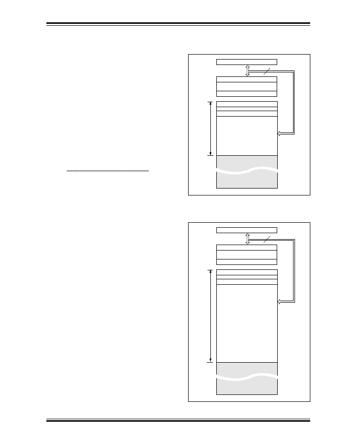
Stack Level 8
Reset Vector
User Memory
Space
Peripheral Interrupt Vector
0000h
0004h
1FFh
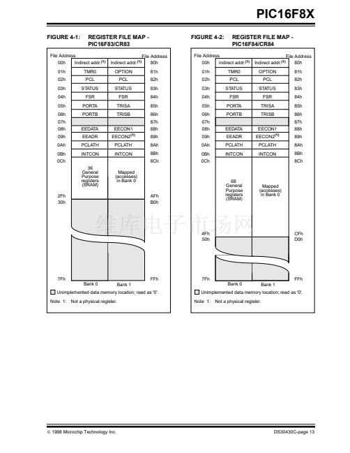
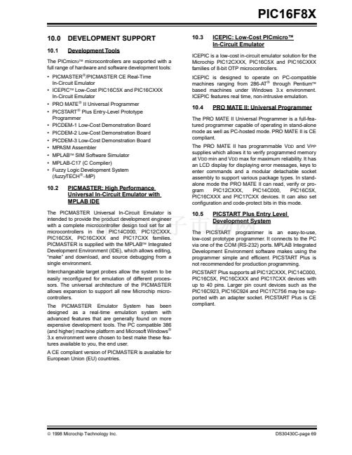
4.1
Program Memory Organization
1FFFh
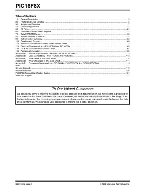
The PIC16FXX has a 13-bit program counter capable
of addressing an 8K x 14 program memory space. For
the PIC16F83 and PIC16CR83, the 铿乺st 512 x 14
(0000h-01FFh)
are
physically
implemented
(Figure 4-1). For the PIC16F84 and PIC16CR84, the
铿乺st 1K x 14 (0000h-03FFh) are physically imple-
mented (Figure 4-2). Accessing a location above the
physically implemented address will cause a wrap-
around. For example, for the PIC16F84 locations 20h,
420h, 820h, C20h, 1020h, 1420h, 1820h, and 1C20h
will be the same instruction.
The reset vector is at 0000h and the interrupt vector is
at 0004h.
FIGURE 4-2:
PROGRAM MEMORY MAP
AND STACK -
PIC16F84/CR84
PC<12:0>
13
CALL, RETURN
RETFIE, RETLW
Stack Level 1
鈥?/div>
鈥?/div>
鈥?/div>
Stack Level 8
Reset Vector
Peripheral Interrupt Vector
0000h
0004h
User Memory
Space
3FFh
1FFFh
漏
1998 Microchip Technology Inc.
DS30430C-page 11


 1
1
 2
2
 3
3
 4
4
 5
5
 6
6
 7
7
 8
8
 9
9
 10
10
 11
11
 12
12
 13
13
 14
14
 15
15
 16
16
 17
17
 18
18
 19
19
 20
20
 21
21
 22
22
 23
23
 24
24
 25
25
 26
26
 27
27
 28
28
 29
29
 30
30
 31
31
 32
32
 33
33
 34
34
 35
35
 36
36
 37
37
 38
38
 39
39
 40
40
 41
41
 42
42
 43
43
 44
44
 45
45
 46
46
 47
47
 48
48
 49
49
 50
50
 51
51
 52
52
 53
53
 54
54
 55
55
 56
56
 57
57
 58
58
 59
59
 60
60
 61
61
 62
62
 63
63
 64
64
 65
65
 66
66
 67
67
 68
68
 69
69
 70
70
 71
71
 72
72
 73
73
 74
74
 75
75
 76
76
 77
77
 78
78
 79
79
 80
80
 81
81
 82
82
 83
83
 84
84
 85
85
 86
86
 87
87
 88
88
 89
89
 90
90
 91
91
 92
92
 93
93
 94
94
 95
95
 96
96
 97
97
 98
98
 99
99
 100
100
 101
101
 102
102
 103
103
 104
104
 105
105
 106
106
 107
107
 108
108
 109
109
 110
110
 111
111
 112
112
 113
113
 114
114
 115
115
 116
116
 117
117
 118
118
 119
119
 120
120
 121
121
 122
122
 123
123
 124
124
