QS5919T
LOW SKEW TTL PLL CLOCK DRIVER WITH INTEGRATED LOOP FILTER
INDUSTRIAL TEMPERATURE RANGE
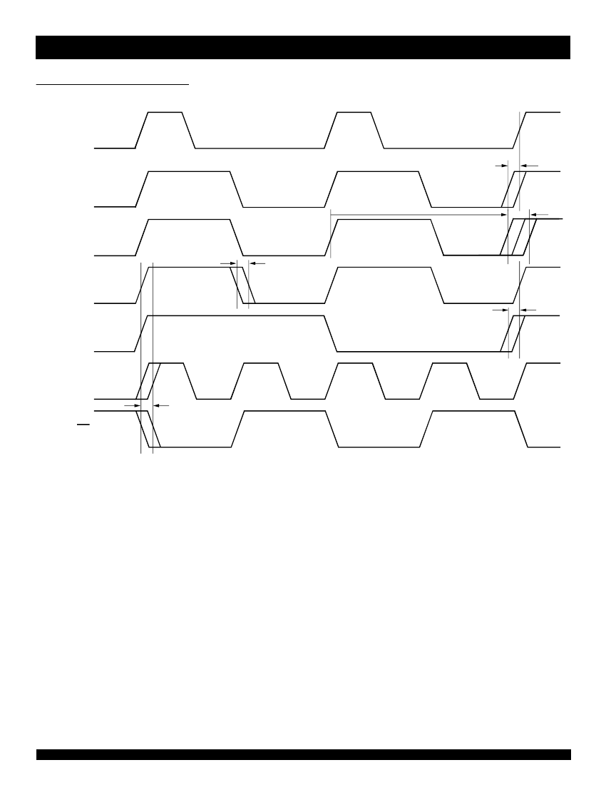
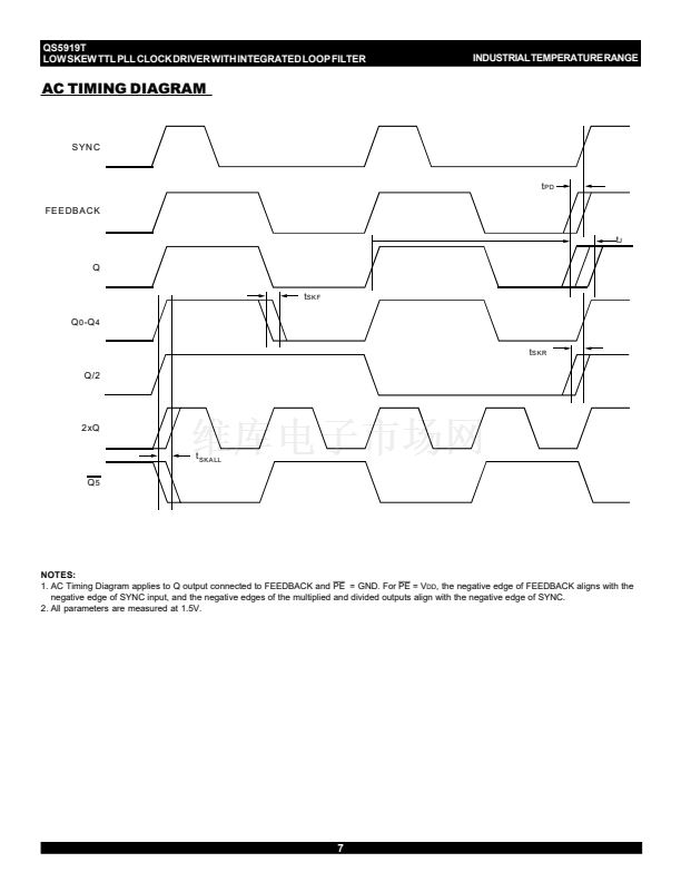
AC TIMING DIAGRAM
SYN C
t
PD
FEEDBACK
t
J
Q
t
SK F
Q
0
-Q
4
t
S KR
Q /2
2xQ
t
SKA LL
Q
5
NOTES:
1. AC Timing Diagram applies to Q output connected to FEEDBACK and
PE
= GND. For
PE
= V
DD
, the negative edge of FEEDBACK aligns with the
negative edge of SYNC input, and the negative edges of the multiplied and divided outputs align with the negative edge of SYNC.
2. All parameters are measured at 1.5V.
7


 1
1
 2
2
 3
3
 4
4
 5
5
 6
6
 7
7
 8
8
 9
9
