OUT4鈭?/div>
PGND4
power ground (substrate)
MGM564
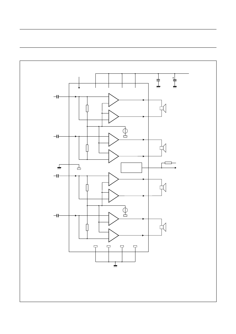
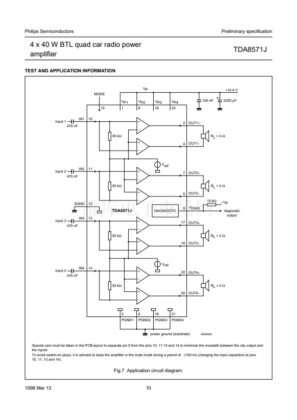
Special care must be taken in the PCB-layout to separate pin 9 from the pins 10, 11 13 and 14 to minimize the crosstalk between the clip output and
the inputs.
To avoid switch-on plops, it is advised to keep the amplifier in the mute mode during a period of
鈮?/div>
150 ms (charging the input capacitors at pins
10, 11, 13 and 14).
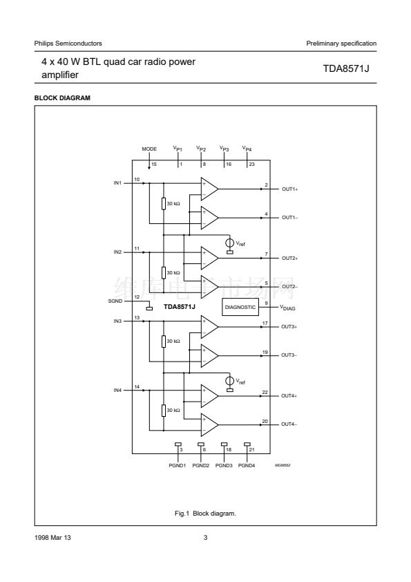
Fig.7 Application circuit diagram.
1998 Mar 13
10


 1
1
 2
2
 3
3
 4
4
 5
5
 6
6
 7
7
 8
8
 9
9
 10
10
 11
11
 12
12
 13
13
 14
14
 15
15
 16
16
 17
17
 18
18
 19
19
 20
20
