TPS23750
TPS23770
SLVS590A 鈥?JULY 2005 鈥?REVISED AUGUST 2005
www.ti.com
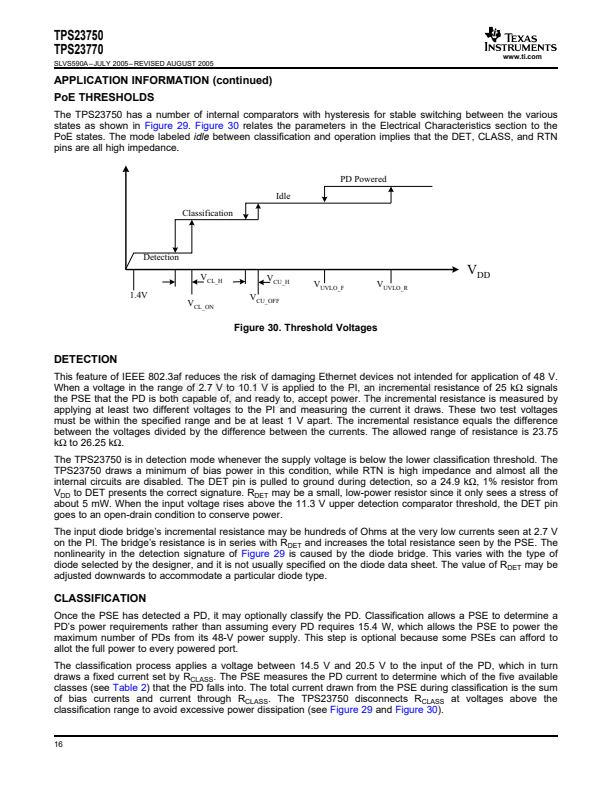
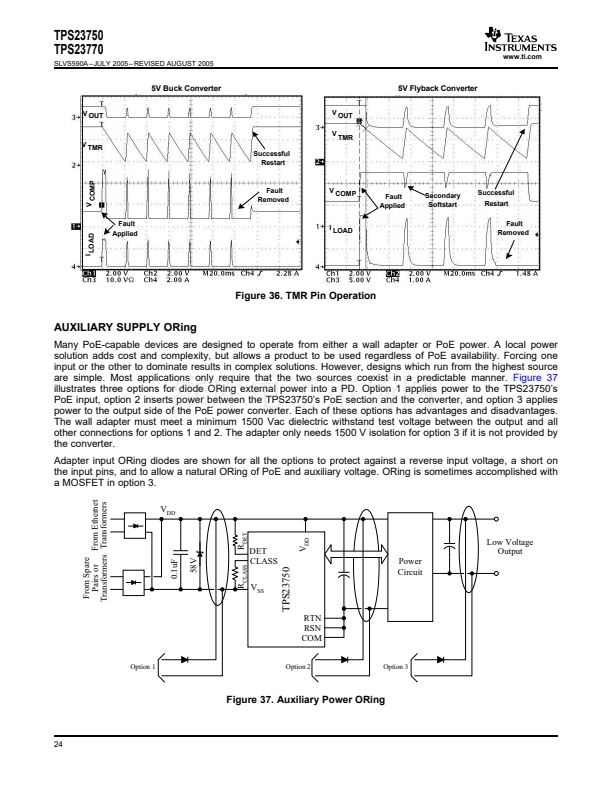
5V Buck Converter
V OUT
V
V
V TMR
Successful
Restart
5V Flyback Converter
OUT
TMR
V COMP
Fault
Removed
V COMP
Fault
Applied
Secondary
Softstart
Successful
Restart
Fault
Removed
I LOAD
Fault
Applied
I LOAD
Figure 36. TMR Pin Operation
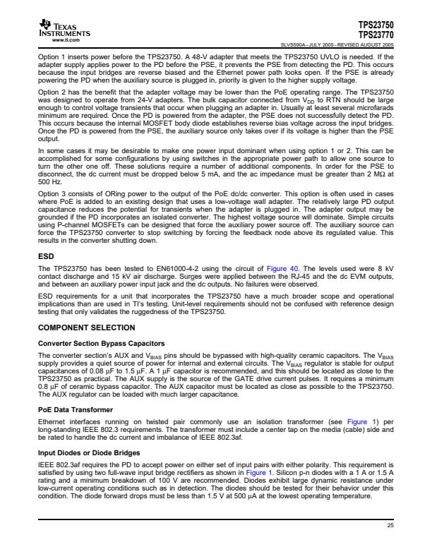
AUXILIARY SUPPLY ORing
Many PoE-capable devices are designed to operate from either a wall adapter or PoE power. A local power
solution adds cost and complexity, but allows a product to be used regardless of PoE availability. Forcing one
input or the other to dominate results in complex solutions. However, designs which run from the highest source
are simple. Most applications only require that the two sources coexist in a predictable manner.
Figure 37
illustrates three options for diode ORing external power into a PD. Option 1 applies power to the TPS23750鈥檚
PoE input, option 2 inserts power between the TPS23750鈥檚 PoE section and the converter, and option 3 applies
power to the output side of the PoE power converter. Each of these options has advantages and disadvantages.
The wall adapter must meet a minimum 1500 Vac dielectric withstand test voltage between the output and all
other connections for options 1 and 2. The adapter only needs 1500 V isolation for option 3 if it is not provided by
the converter.
Adapter input ORing diodes are shown for all the options to protect against a reverse input voltage, a short on
the input pins, and to allow a natural ORing of PoE and auxiliary voltage. ORing is sometimes accomplished with
a MOSFET in option 3.
From Spare
Pairs or From Ethernet
Transformers Transformers
V
DD
R
DET
V
DD
58V
0.1uF
R
CLASS
DET
CLASS
V
SS
Low Voltage
Output
Power
Circuit
TPS23750
RTN
RSN
COM
Option 2
Option
1
Option 3
Figure 37. Auxiliary Power ORing
24


 1
1
 2
2
 3
3
 4
4
 5
5
 6
6
 7
7
 8
8
 9
9
 10
10
 11
11
 12
12
 13
13
 14
14
 15
15
 16
16
 17
17
 18
18
 19
19
 20
20
 21
21
 22
22
 23
23
 24
24
 25
25
 26
26
 27
27
 28
28
 29
29
 30
30
 31
31
 32
32
 33
33
 34
34
 35
35
 36
36
 37
37
 38
38
