鈥?/div>
G
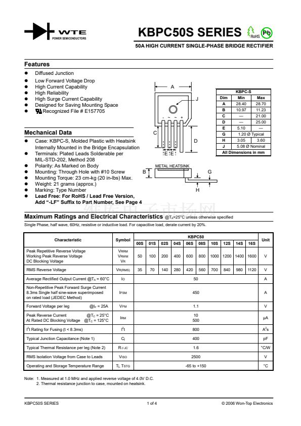
1.20 脴 Typical
H
3.05
3.60
J
5.08 脴 Nominal
All Dimensions in mm
KBPC-S
Min
- ~ ~ +
Mechanical Data
Case: KBPC-S, Molded Plastic with Heatsink
Internally Mounted in the Bridge Encapsulation
Terminals: Plated Leads Solderable per
MIL-STD-202, Method 208
Polarity: As Marked on Body
Mounting: Through Hole with #10 Screw
B
Mounting Torque: 23 cm-kg (20 in-lbs) Max.
Weight: 21 grams (approx.)
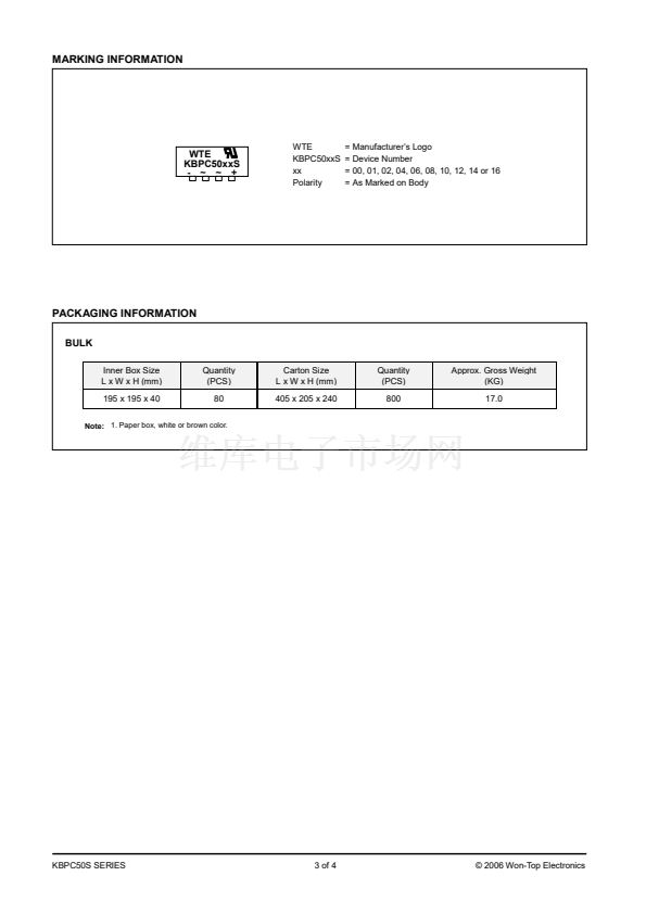
Marking: Type Number
Lead Free: For RoHS / Lead Free Version,
Add 鈥?LF鈥?Suffix to Part Number, See Page 4
C
D
E E
METAL HEATSINK
G
H
Maximum Ratings and Electrical Characteristics
@T
A
=25掳C unless otherwise specified
Single Phase, half wave, 60Hz, resistive or inductive load. For capacitive load, derate current by 20%.
KBPC50
00S
Peak Repetitive Reverse Voltage
Working Peak Reverse Voltage
DC Blocking Voltage
RMS Reverse Voltage
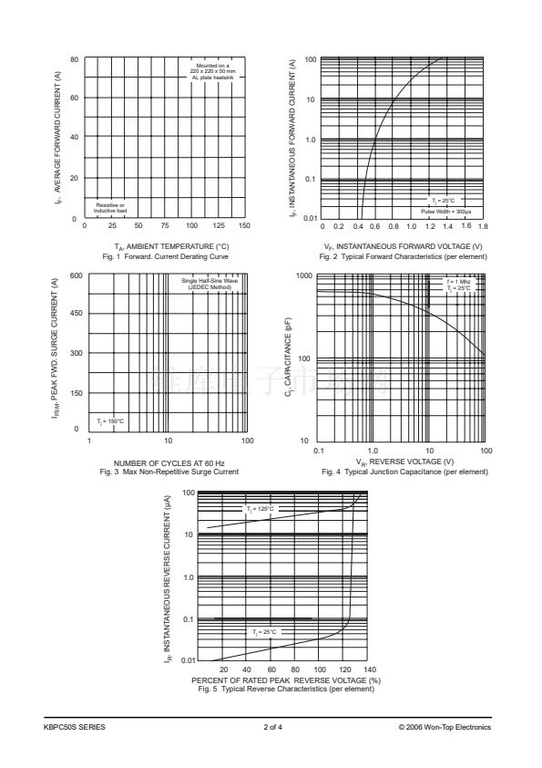
Average Rectified Output Current @T
A
= 60掳C
Non-Repetitive Peak Forward Surge Current
8.3ms Single half sine-wave superimposed
on rated load (JEDEC Method)
Forward Voltage per leg
@I
F
= 25A
V
RRM
V
RWM
V
R
V
R(RMS)
I
O
I
FSM
V
FM
I
RM
I
2
t
C
j
R
胃JC
V
ISO
T
j
, T
STG
50
35
01S
100
70
02S
200
140
04S
400
280
06S
600
420
50
450
1.1
10
500
800
400
1.6
2500
-65 to +150
08S
800
560
10S
12S
14S
16S
V
V
A
A
V
碌A
A
2
s
pF
掳C/W
V
掳C
Characteristic
Symbol
Unit
1000 1200 1400 1600
700
840
980
1120
Peak Reverse Current
@T
C
= 25掳C
At Rated DC Blocking Voltage @T
C
= 125掳C
I
2
t Rating for Fusing (t < 8.3ms)
Typical Junction Capacitance (Note 1)
Typical Thermal Resistance per leg (Note 2)
RMS Isolation Voltage from Case to Leads
Operating and Storage Temperature Range
Note: 1. Measured at 1.0 MHz and applied reverse voltage of 4.0V D.C.
2. Thermal resistance junction to case, mounted on heatsink.
KBPC50S SERIES
1 of 4
漏 2006 Won-Top Electronics


 1
1
 2
2
 3
3
 4
4
