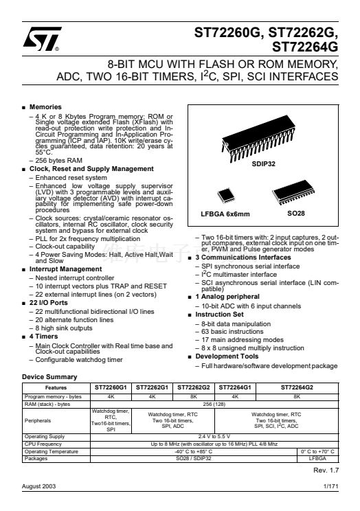
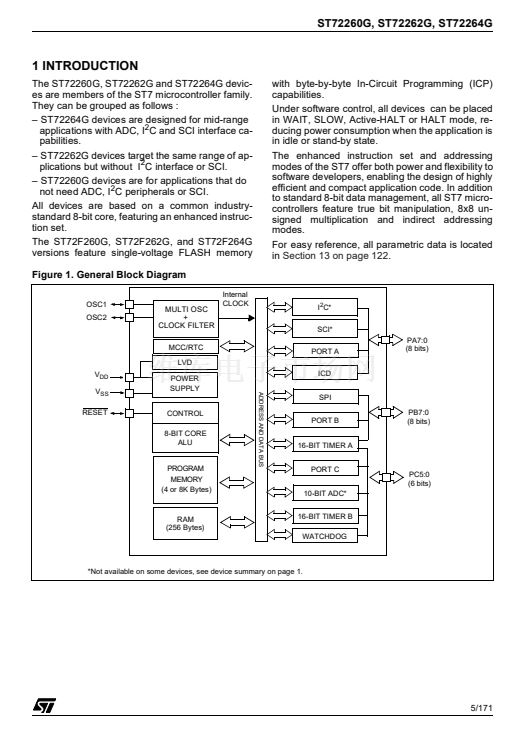
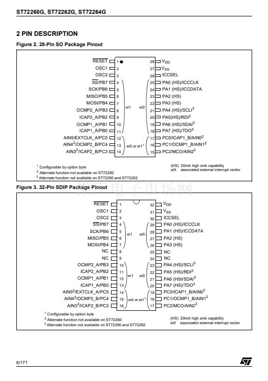
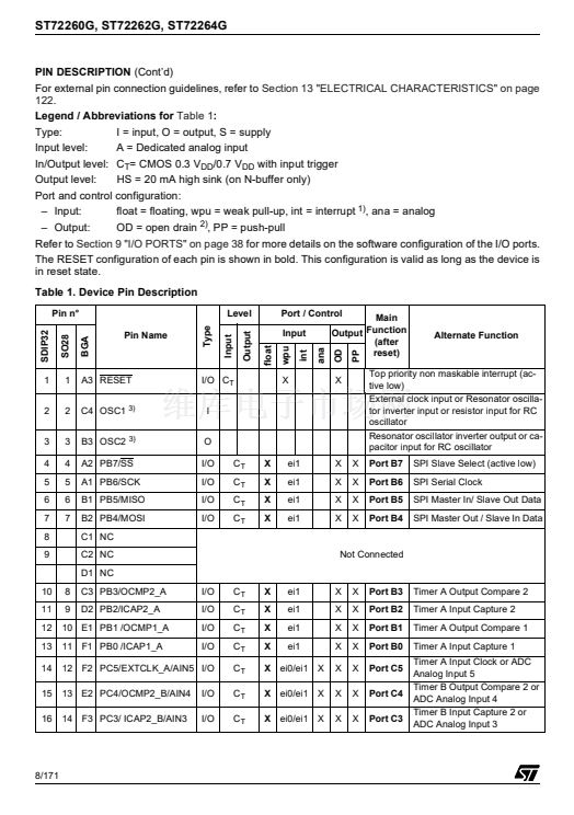
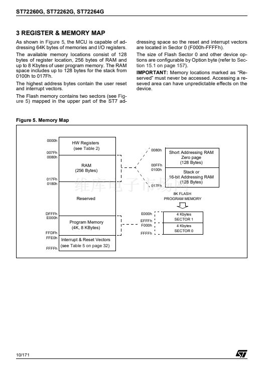
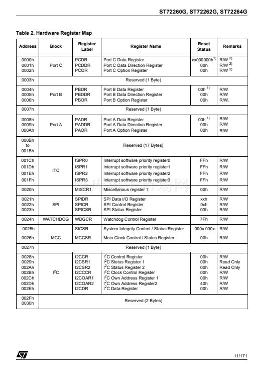
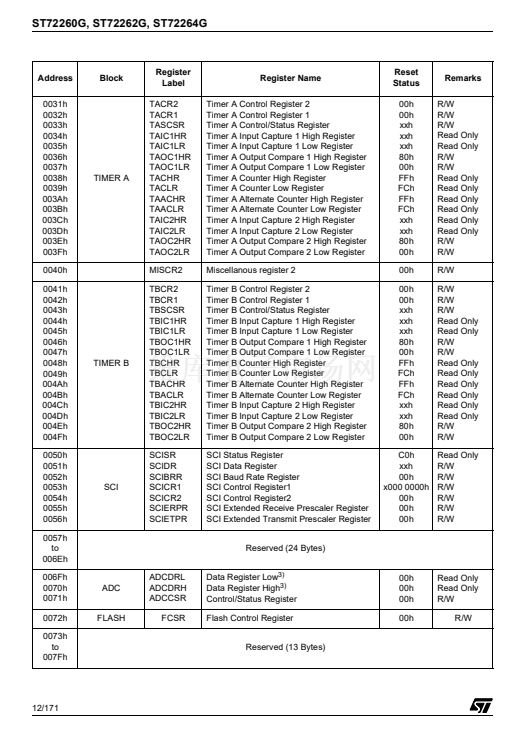
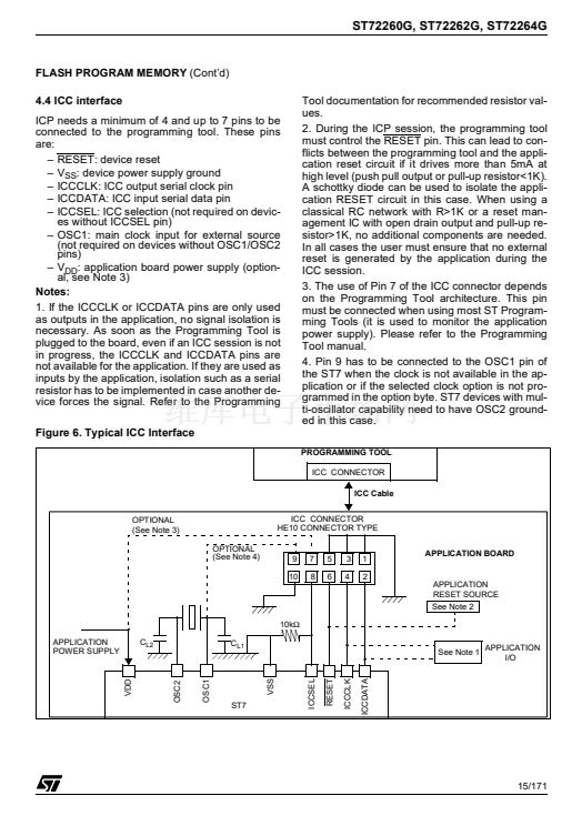
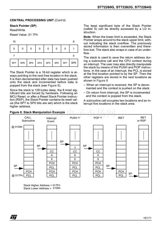
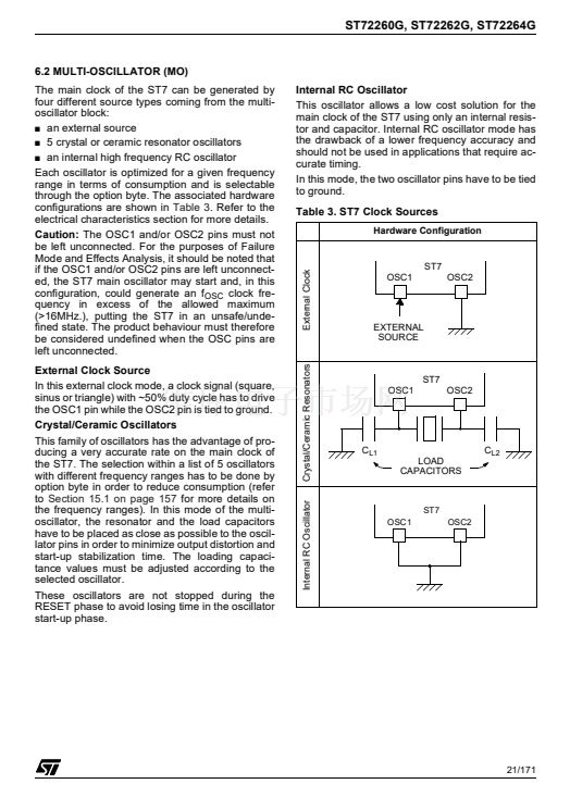
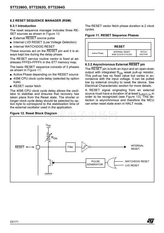
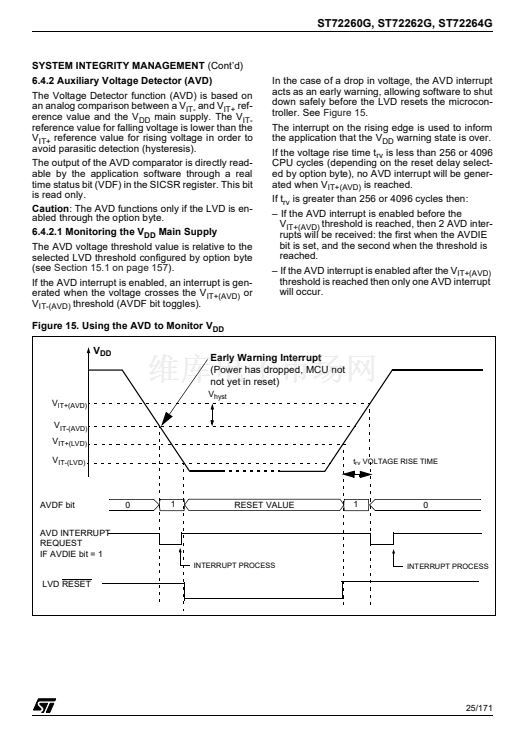
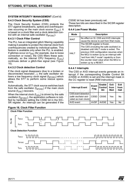
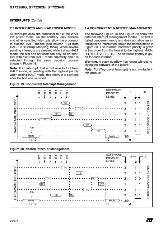
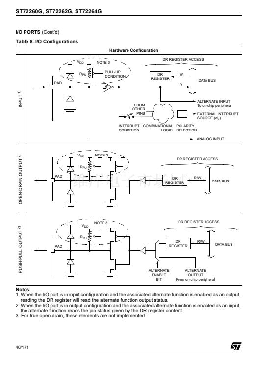
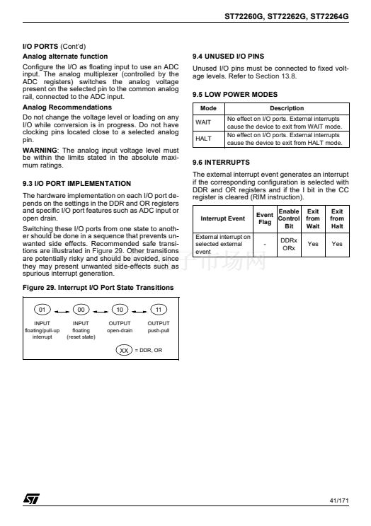
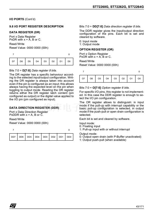
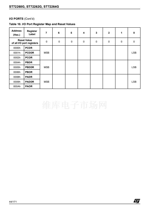
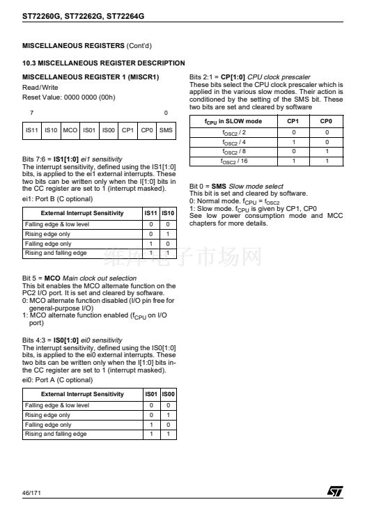
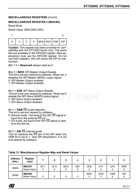
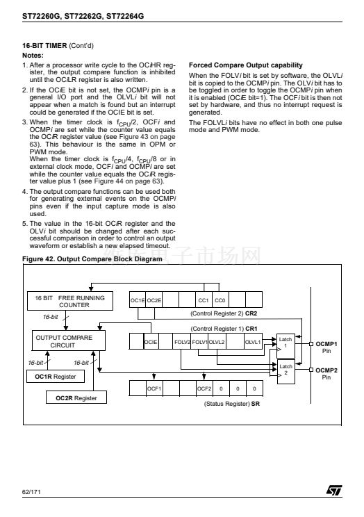
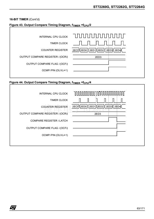
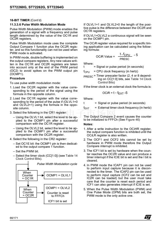
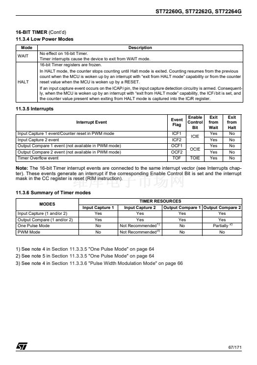
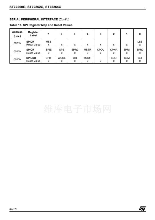
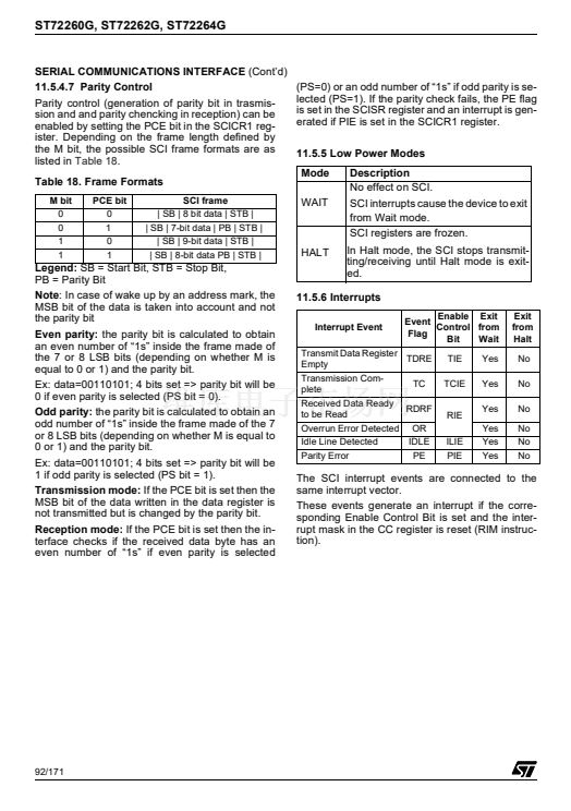
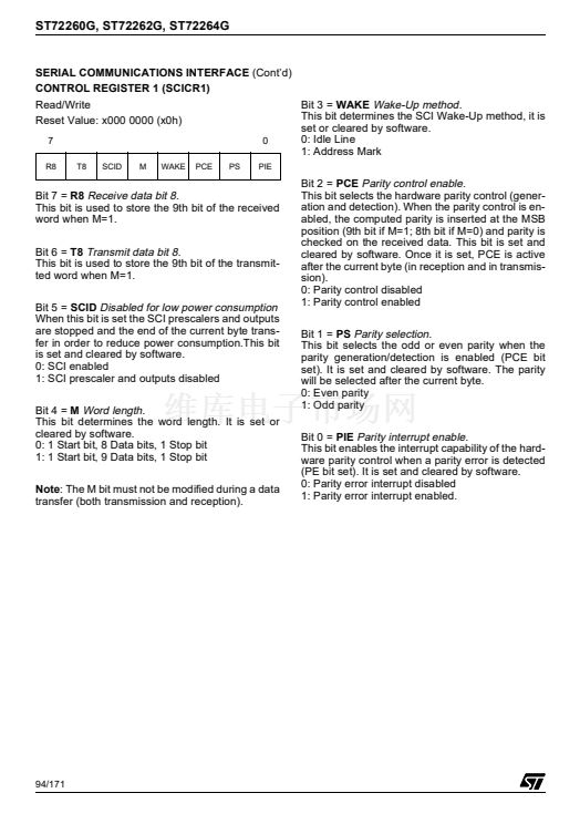
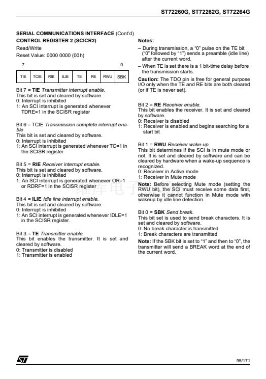
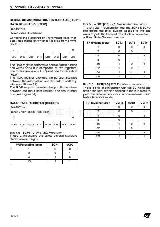
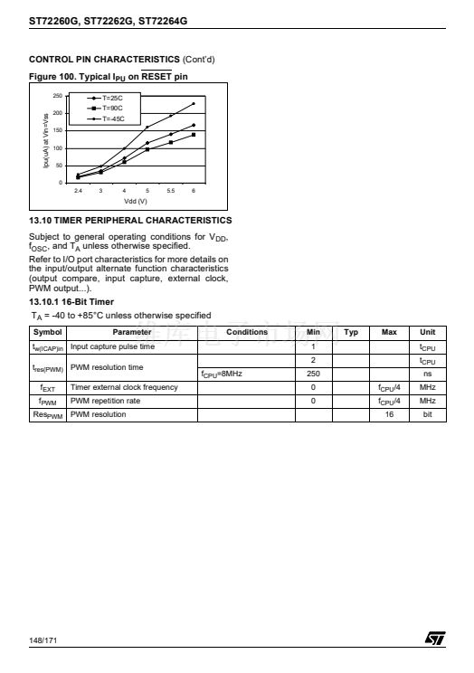
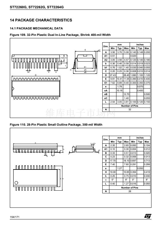
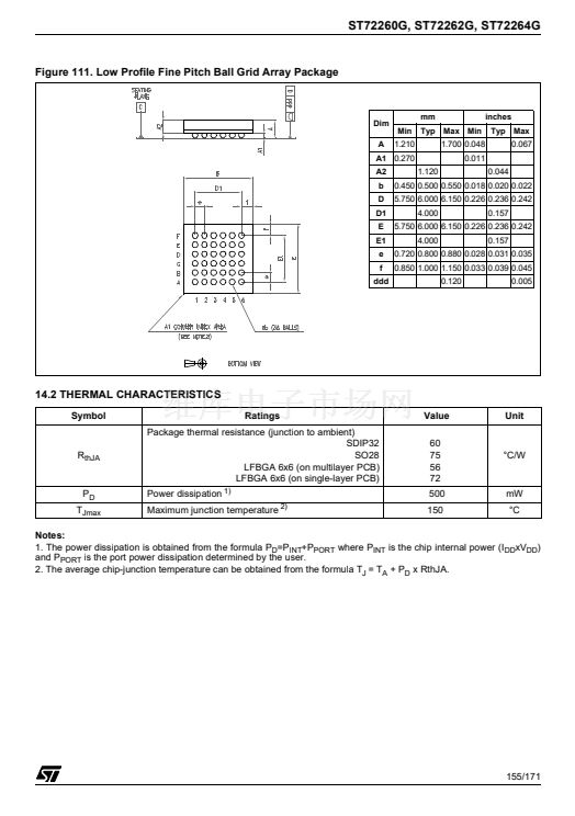
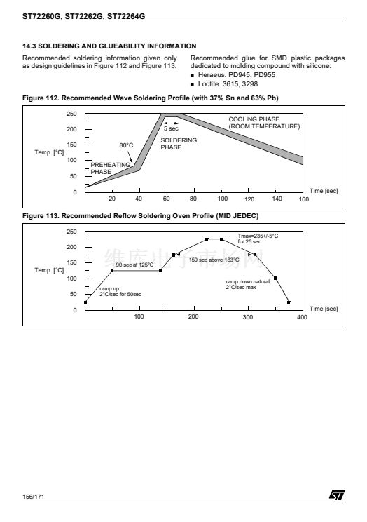
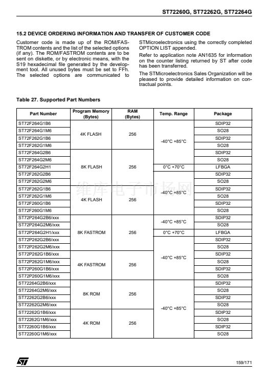
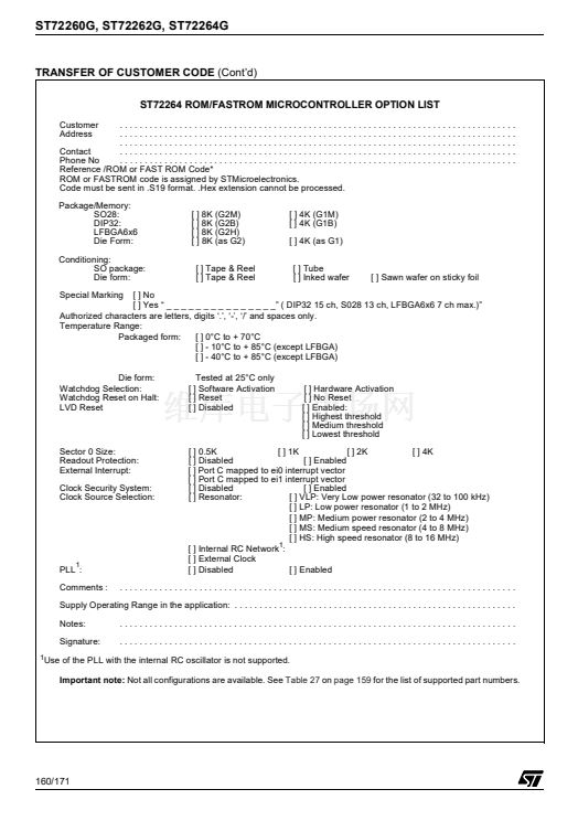
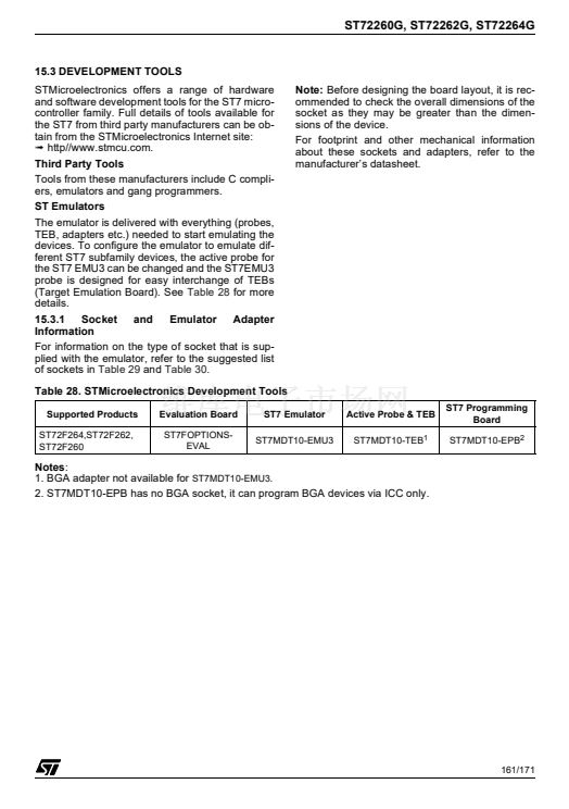
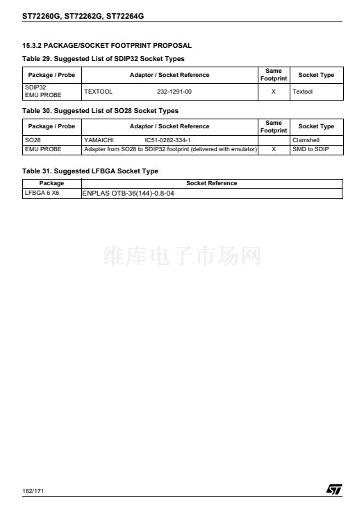
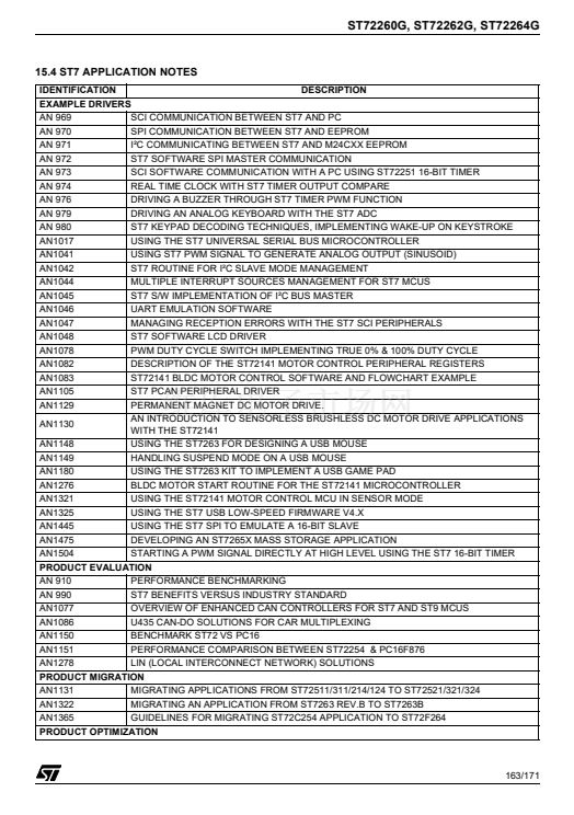
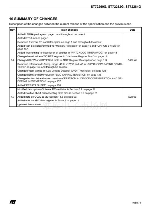
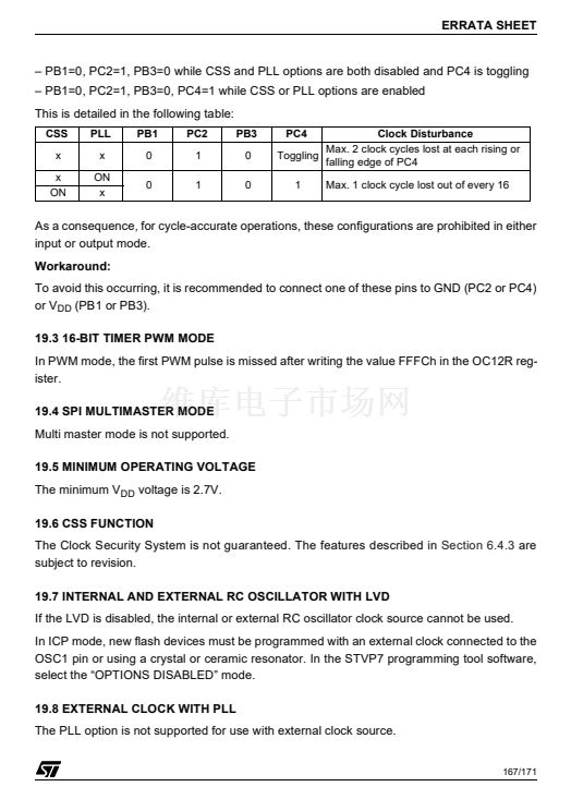
ST72260G, ST72262G, ST72264G
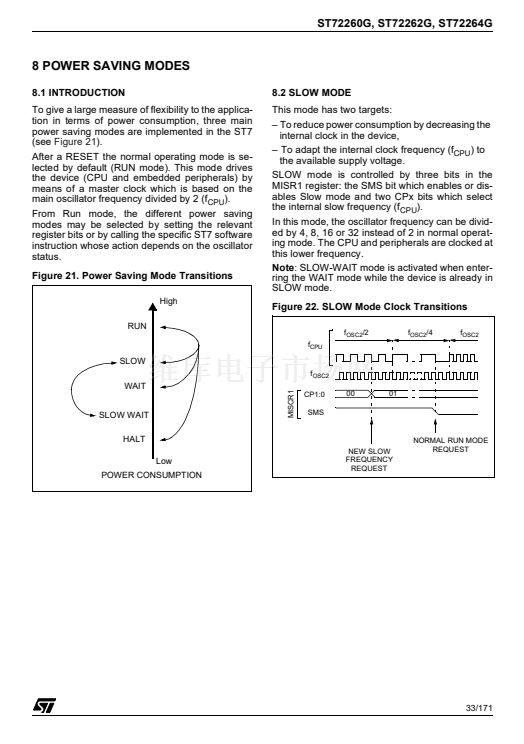
POWER SAVING MODES
(Cont鈥檇)
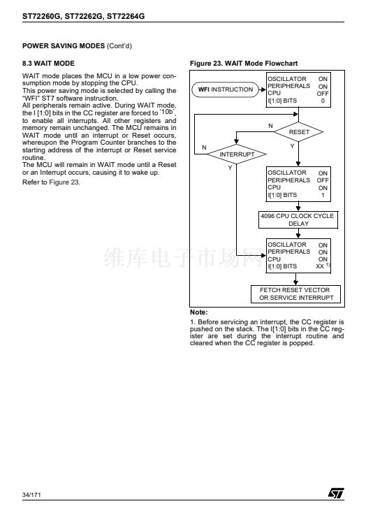
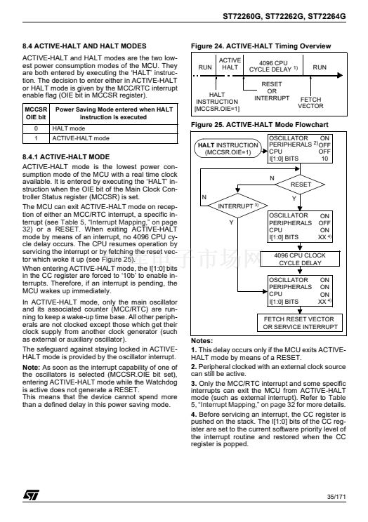
8.5 HALT MODE
The HALT mode is the lowest power consumption
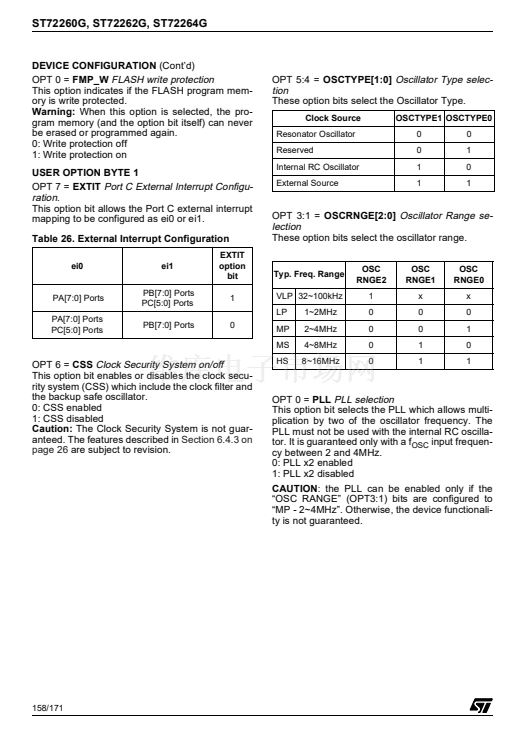
mode of the MCU. It is entered by executing the
ST7 HALT instruction (see
Figure 27).
The MCU can exit HALT mode on reception of ei-
ther a specific interrupt (see
Table 5, 鈥淚nterrupt
Mapping,鈥?on page 32)
or a RESET. When exiting
HALT mode by means of a RESET or an interrupt,
the oscillator is immediately turned on and the
4096 CPU cycle delay is used to stabilize the os-
cillator. After the start up delay, the CPU resumes
operation by servicing the interrupt or by fetching
the reset vector which woke it up (see
Figure 26).
When entering HALT mode, the I[1:0] bits in the
CC register are forced to 鈥?0b鈥?to enable interrupts.
Therefore, if an interrupt is pending, the MCU
wakes immediately.
In the HALT mode the main oscillator is turned off
causing all internal processing to be stopped, in-
cluding the operation of the on-chip peripherals.
All peripherals are not clocked except the ones
which get their clock supply from another clock
generator (such as an external or auxiliary oscilla-
tor).
The compatibility of Watchdog operation with
HALT mode is configured by the 鈥淲DGHALT鈥?op-
tion bit of the option byte. The HALT instruction
when executed while the Watchdog system is en-
abled, can generate a Watchdog RESET (see
Section 15.1 "OPTION BYTES" on page 157
for
more details).
Figure 26. HALT Mode Timing Overview
RUN
HALT
4096 CPU CYCLE
DELAY
RUN
FETCH RESET VECTOR
OR SERVICE INTERRUPT
Figure 27. HALT Mode Flowchart
HALT
INSTRUCTION
ENABLE
WDGHALT
1)
1
WATCHDOG
RESET
OSCILLATOR
OFF
2)
PERIPHERALS OFF
CPU
OFF
0
I[1:0] BITS
0
WATCHDOG
DISABLE
N
RESET
N
INTERRUPT
Y
Y
3)
OSCILLATOR
PERIPHERALS
CPU
I[1:0] BITS
ON
OFF
ON
1
4096 CPU CLOCK CYCLE
DELAY
OSCILLATOR
PERIPHERALS
CPU
I[1:0] BITS
ON
ON
ON
XX
4)
HALT
INSTRUCTION
RESET
OR
INTERRUPT
FETCH
VECTOR
Notes:
1. WDGHALT is an option bit. See option byte sec-
tion for more details.
2. Peripheral clocked with an external clock source
can still be active.
3. Only some specific interrupts can exit the MCU
from HALT mode (such as external interrupt). Re-
fer to
Table 5, 鈥淚nterrupt Mapping,鈥?on page 32
for
more details.
4. Before servicing an interrupt, the CC register is
pushed on the stack. The I[1:0]
bits
in the CC reg-
ister are set during the interrupt routine and
cleared when the CC register is popped.
36/171


 1
1
 2
2
 3
3
 4
4
 5
5
 6
6
 7
7
 8
8
 9
9
 10
10
 11
11
 12
12
 13
13
 14
14
 15
15
 16
16
 17
17
 18
18
 19
19
 20
20
 21
21
 22
22
 23
23
 24
24
 25
25
 26
26
 27
27
 28
28
 29
29
 30
30
 31
31
 32
32
 33
33
 34
34
 35
35
 36
36
 37
37
 38
38
 39
39
 40
40
 41
41
 42
42
 43
43
 44
44
 45
45
 46
46
 47
47
 48
48
 49
49
 50
50
 51
51
 52
52
 53
53
 54
54
 55
55
 56
56
 57
57
 58
58
 59
59
 60
60
 61
61
 62
62
 63
63
 64
64
 65
65
 66
66
 67
67
 68
68
 69
69
 70
70
 71
71
 72
72
 73
73
 74
74
 75
75
 76
76
 77
77
 78
78
 79
79
 80
80
 81
81
 82
82
 83
83
 84
84
 85
85
 86
86
 87
87
 88
88
 89
89
 90
90
 91
91
 92
92
 93
93
 94
94
 95
95
 96
96
 97
97
 98
98
 99
99
 100
100
 101
101
 102
102
 103
103
 104
104
 105
105
 106
106
 107
107
 108
108
 109
109
 110
110
 111
111
 112
112
 113
113
 114
114
 115
115
 116
116
 117
117
 118
118
 119
119
 120
120
 121
121
 122
122
 123
123
 124
124
 125
125
 126
126
 127
127
 128
128
 129
129
 130
130
 131
131
 132
132
 133
133
 134
134
 135
135
 136
136
 137
137
 138
138
 139
139
 140
140
 141
141
 142
142
 143
143
 144
144
 145
145
 146
146
 147
147
 148
148
 149
149
 150
150
 151
151
 152
152
 153
153
 154
154
 155
155
 156
156
 157
157
 158
158
 159
159
 160
160
 161
161
 162
162
 163
163
 164
164
 165
165
 166
166
 167
167
 168
168
 169
169
 170
170
 171
171
