ST72260G, ST72262G, ST72264G
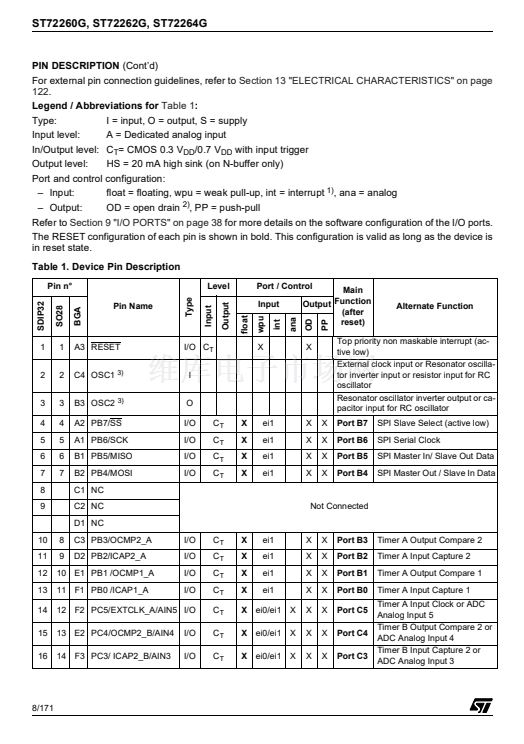
I/O PORTS
(Cont鈥檇)
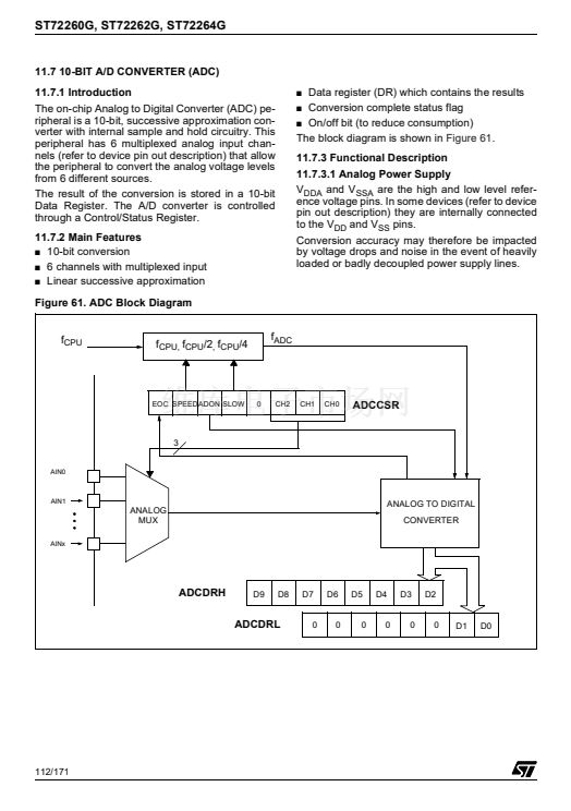
Analog alternate function
Configure the I/O as floating input to use an ADC
input. The analog multiplexer (controlled by the
ADC registers) switches the analog voltage
present on the selected pin to the common analog
rail, connected to the ADC input.
Analog Recommendations
Do not change the voltage level or loading on any
I/O while conversion is in progress. Do not have
clocking pins located close to a selected analog
pin.
WARNING:
The analog input voltage level must
be within the limits stated in the absolute maxi-
mum ratings.
9.3 I/O PORT IMPLEMENTATION
The hardware implementation on each I/O port de-
pends on the settings in the DDR and OR registers
and specific I/O port features such as ADC input or
open drain.
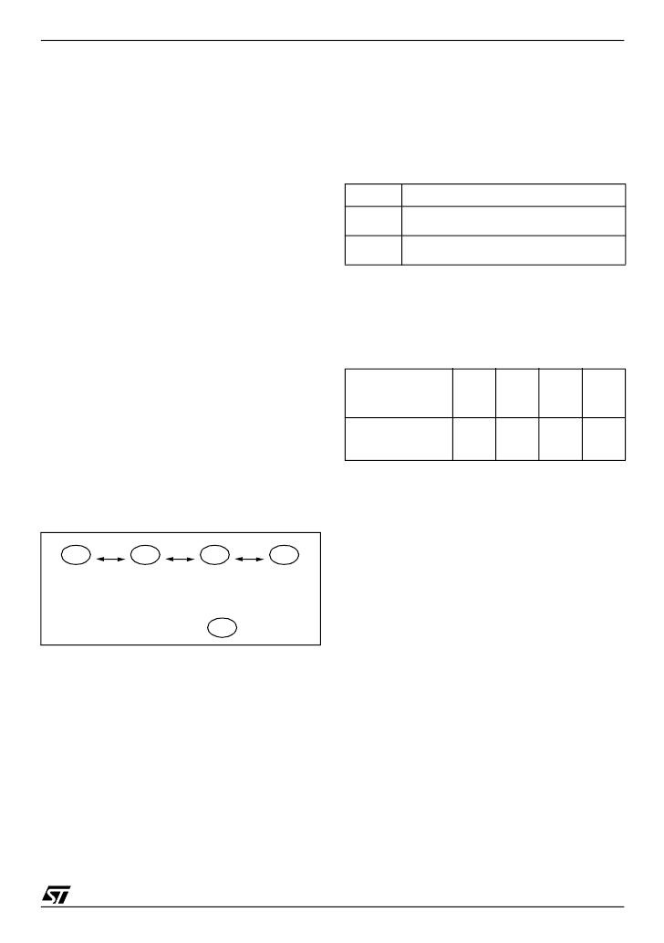
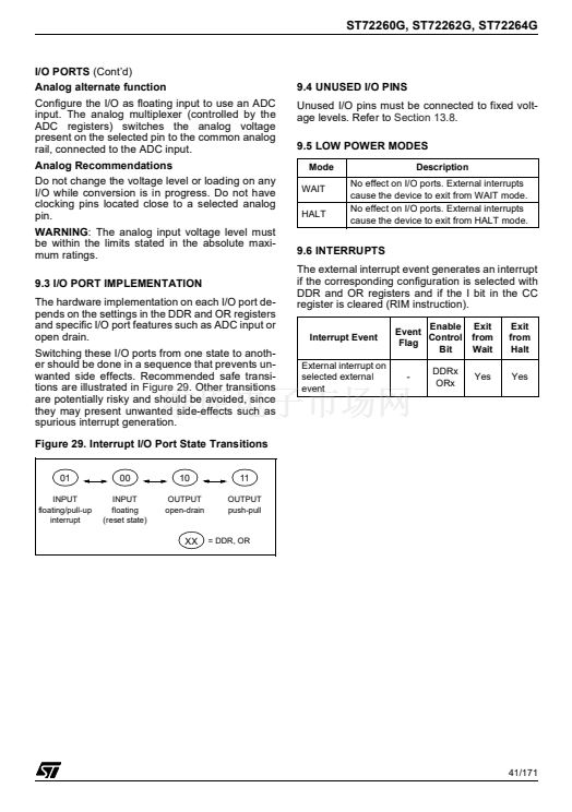
Switching these I/O ports from one state to anoth-
er should be done in a sequence that prevents un-
wanted side effects. Recommended safe transi-
tions are illustrated in
Figure 29.
Other transitions
are potentially risky and should be avoided, since
they may present unwanted side-effects such as
spurious interrupt generation.
Figure 29. Interrupt I/O Port State Transitions
01
INPUT
floating/pull-up
interrupt
9.4 UNUSED I/O PINS
Unused I/O pins must be connected to fixed volt-
age levels. Refer to
Section 13.8.
9.5 LOW POWER MODES
Mode
WAIT
HALT
Description
No effect on I/O ports. External interrupts
cause the device to exit from WAIT mode.
No effect on I/O ports. External interrupts
cause the device to exit from HALT mode.
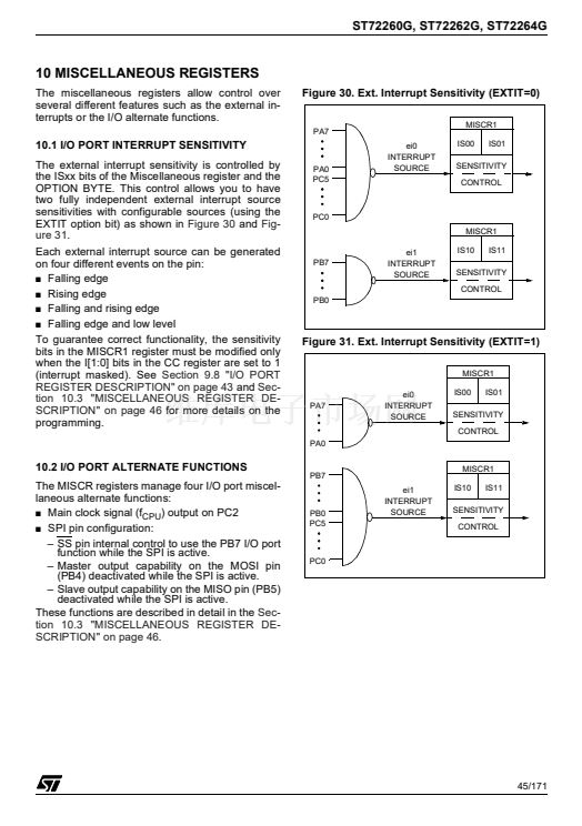
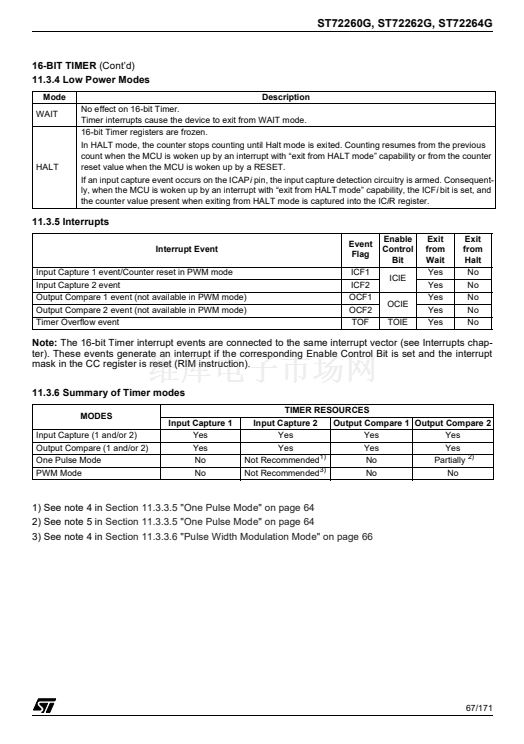
9.6 INTERRUPTS
The external interrupt event generates an interrupt
if the corresponding configuration is selected with
DDR and OR registers and if the I bit in the CC
register is cleared (RIM instruction).
Interrupt Event
External interrupt on
selected external
event
Enable
Event
Control
Flag
Bit
-
DDRx
ORx
Exit
from
Wait
Yes
Exit
from
Halt
Yes
00
INPUT
floating
(reset state)
10
OUTPUT
open-drain
11
OUTPUT
push-pull
XX
= DDR, OR
41/171


 1
1
 2
2
 3
3
 4
4
 5
5
 6
6
 7
7
 8
8
 9
9
 10
10
 11
11
 12
12
 13
13
 14
14
 15
15
 16
16
 17
17
 18
18
 19
19
 20
20
 21
21
 22
22
 23
23
 24
24
 25
25
 26
26
 27
27
 28
28
 29
29
 30
30
 31
31
 32
32
 33
33
 34
34
 35
35
 36
36
 37
37
 38
38
 39
39
 40
40
 41
41
 42
42
 43
43
 44
44
 45
45
 46
46
 47
47
 48
48
 49
49
 50
50
 51
51
 52
52
 53
53
 54
54
 55
55
 56
56
 57
57
 58
58
 59
59
 60
60
 61
61
 62
62
 63
63
 64
64
 65
65
 66
66
 67
67
 68
68
 69
69
 70
70
 71
71
 72
72
 73
73
 74
74
 75
75
 76
76
 77
77
 78
78
 79
79
 80
80
 81
81
 82
82
 83
83
 84
84
 85
85
 86
86
 87
87
 88
88
 89
89
 90
90
 91
91
 92
92
 93
93
 94
94
 95
95
 96
96
 97
97
 98
98
 99
99
 100
100
 101
101
 102
102
 103
103
 104
104
 105
105
 106
106
 107
107
 108
108
 109
109
 110
110
 111
111
 112
112
 113
113
 114
114
 115
115
 116
116
 117
117
 118
118
 119
119
 120
120
 121
121
 122
122
 123
123
 124
124
 125
125
 126
126
 127
127
 128
128
 129
129
 130
130
 131
131
 132
132
 133
133
 134
134
 135
135
 136
136
 137
137
 138
138
 139
139
 140
140
 141
141
 142
142
 143
143
 144
144
 145
145
 146
146
 147
147
 148
148
 149
149
 150
150
 151
151
 152
152
 153
153
 154
154
 155
155
 156
156
 157
157
 158
158
 159
159
 160
160
 161
161
 162
162
 163
163
 164
164
 165
165
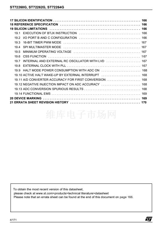
 166
166
 167
167
 168
168
 169
169
 170
170
 171
171
