ST72260G, ST72262G, ST72264G
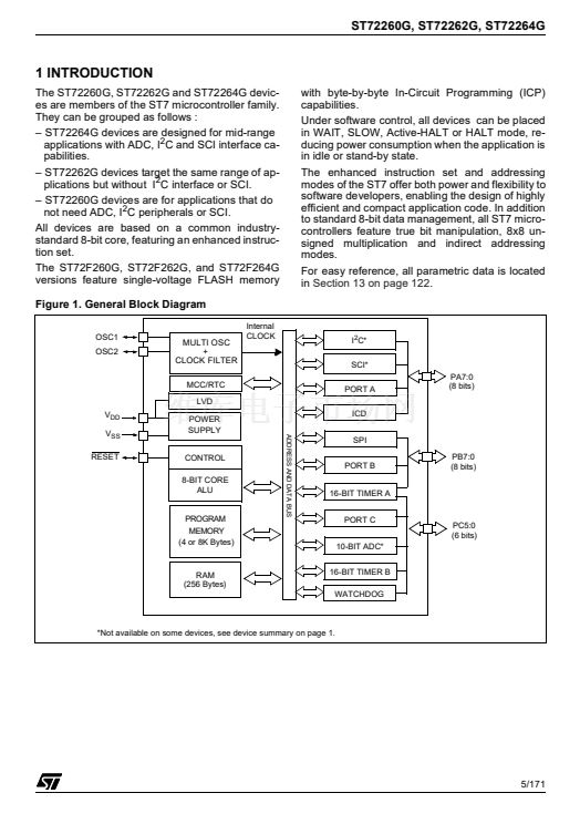
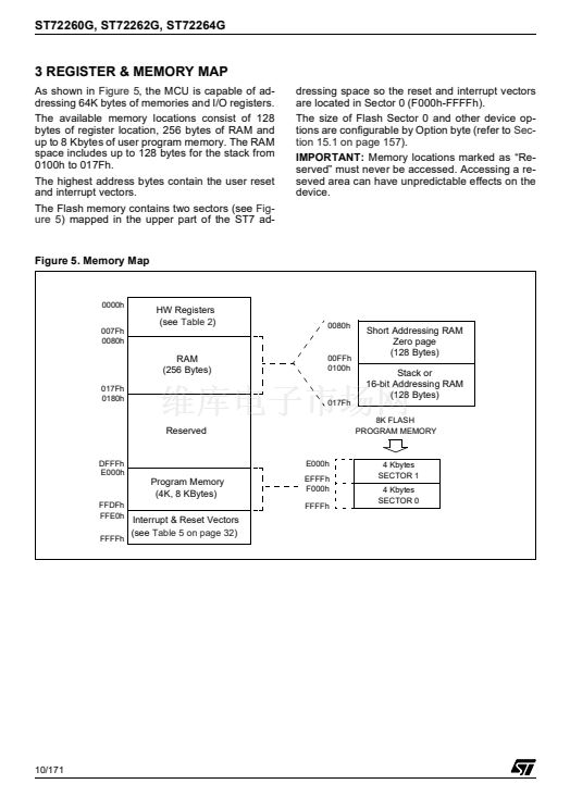
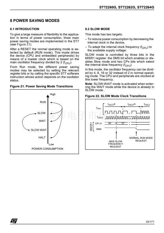
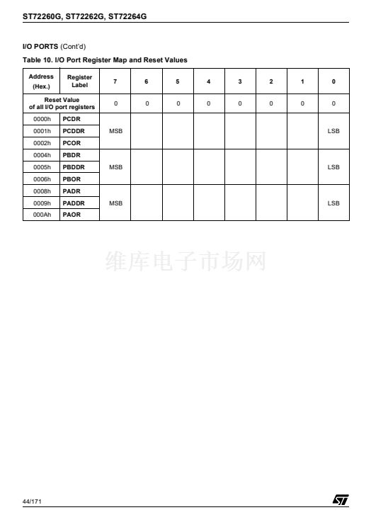
11 ON-CHIP PERIPHERALS
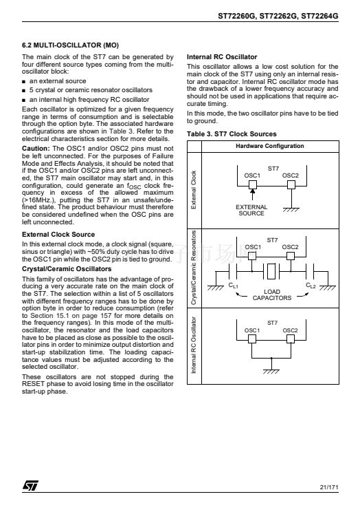
11.1 WATCHDOG TIMER (WDG)
11.1.1 Introduction
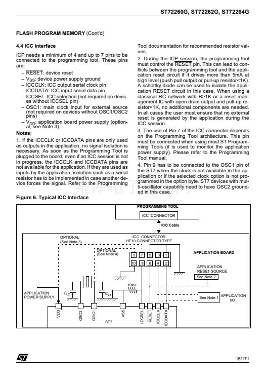
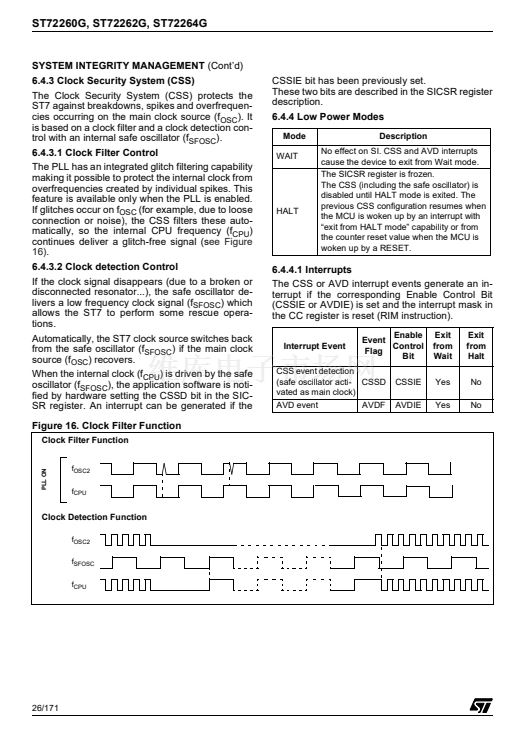
The Watchdog timer is used to detect the occur-
rence of a software fault, usually generated by ex-
ternal interference or by unforeseen logical condi-
tions, which causes the application program to
abandon its normal sequence. The Watchdog cir-
cuit generates an MCU reset on expiry of a pro-
grammed time period, unless the program refresh-
es the counter鈥檚 contents before the T6 bit be-
comes cleared.
11.1.2 Main Features
s
Programmable free-running downcounter
s
Programmable reset
s
Reset (if watchdog activated) when the T6 bit
reaches zero
s
Optional
reset
on
HALT
instruction
(configurable by option byte)
s
Hardware Watchdog selectable by option byte
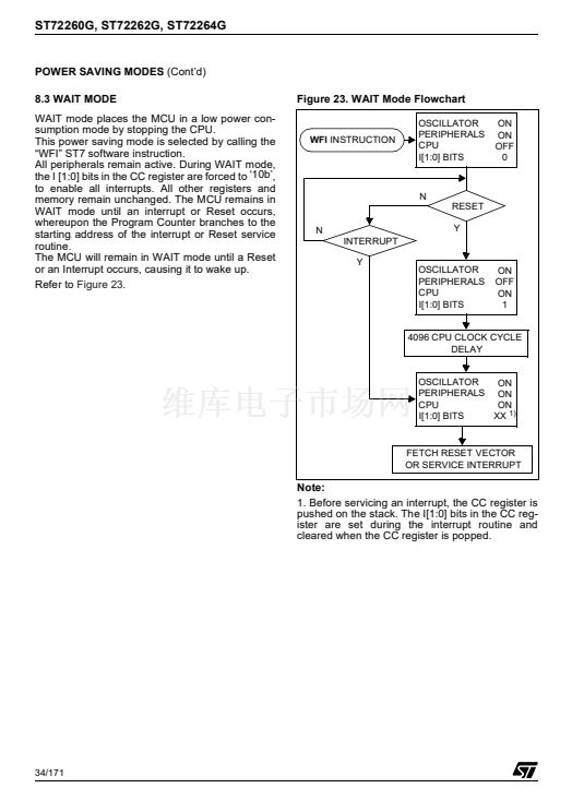
11.1.3 Functional Description
The counter value stored in the Watchdog Control
register (WDGCR bits T[6:0]), is decremented
every 16384 f
OSC2
cycles (approx.), and the
length of the timeout period can be programmed
by the user in 64 increments.
If the watchdog is activated (the WDGA bit is set)
and when the 7-bit timer (bits T[6:0]) rolls over
from 40h to 3Fh (T6 becomes cleared), it initiates
a reset cycle pulling low the reset pin for typically
500ns.
The application program must write in the
WDGCR register at regular intervals during normal
operation to prevent an MCU reset. This down-
counter is free-running: it counts down even if the
watchdog is disabled. The value to be stored in the
WDGCR register must be between FFh and C0h:
鈥?The WDGA bit is set (watchdog enabled)
鈥?The T6 bit is set to prevent generating an imme-
diate reset
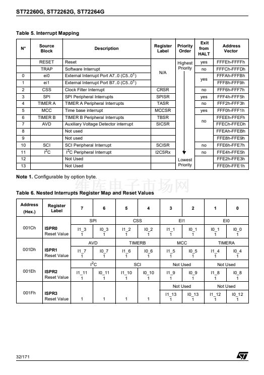
鈥?The T[5:0] bits contain the number of increments
which represents the time delay before the
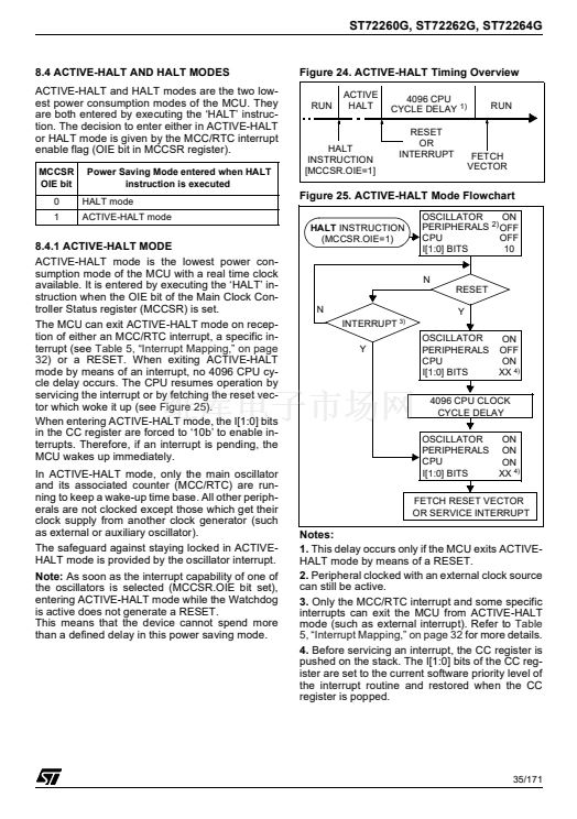
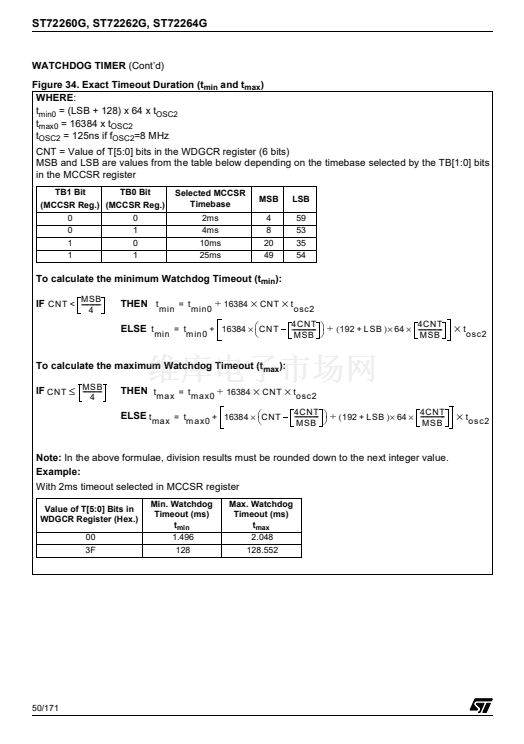
watchdog produces a reset (see
Figure 33. Ap-
proximate Timeout Duration).
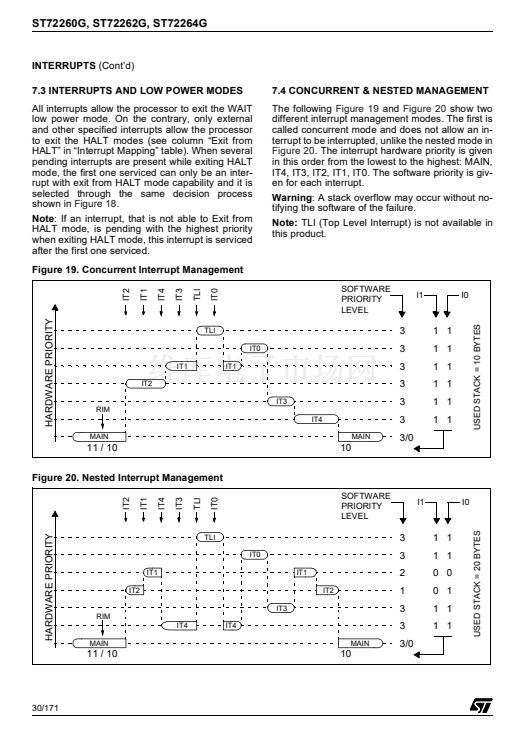
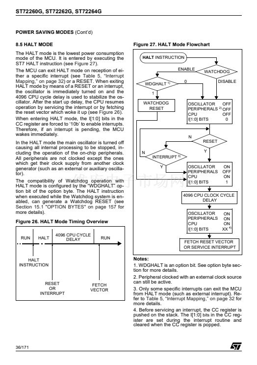
The timing varies
between a minimum and a maximum value due
to the unknown status of the prescaler when writ-
ing to the WDGCR register (see
Figure 34).
Following a reset, the watchdog is disabled. Once
activated it cannot be disabled, except by a reset.
The T6 bit can be used to generate a software re-
set (the WDGA bit is set and the T6 bit is cleared).
If the watchdog is activated, the HALT instruction
will generate a Reset.
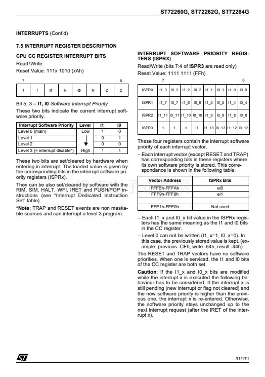
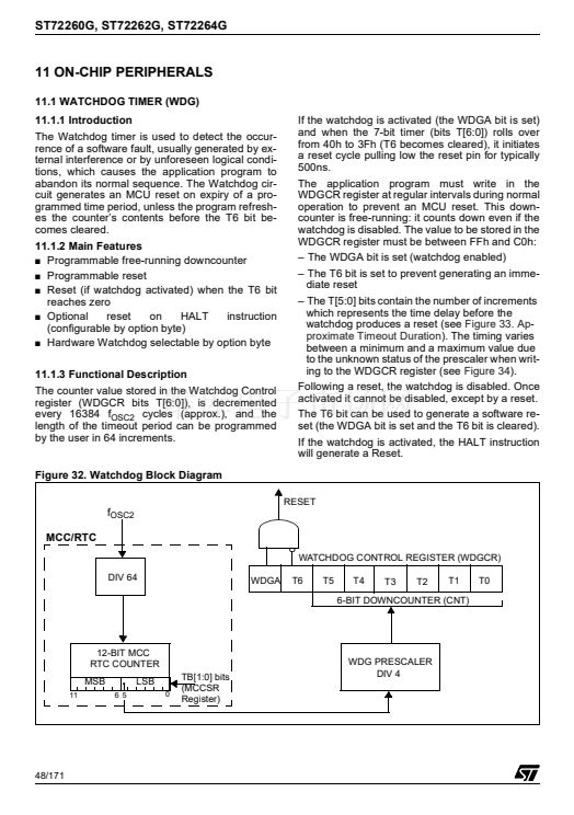
Figure 32. Watchdog Block Diagram
RESET
f
OSC2
MCC/RTC
WATCHDOG CONTROL REGISTER (WDGCR)
DIV 64
WDGA
T6
T5
T4
T3
T2
T1
T0
6-BIT DOWNCOUNTER (CNT)
12-BIT MCC
RTC COUNTER
MSB
11
6 5
LSB
0
TB[1:0] bits
(MCCSR
Register)
WDG PRESCALER
DIV 4
48/171


 1
1
 2
2
 3
3
 4
4
 5
5
 6
6
 7
7
 8
8
 9
9
 10
10
 11
11
 12
12
 13
13
 14
14
 15
15
 16
16
 17
17
 18
18
 19
19
 20
20
 21
21
 22
22
 23
23
 24
24
 25
25
 26
26
 27
27
 28
28
 29
29
 30
30
 31
31
 32
32
 33
33
 34
34
 35
35
 36
36
 37
37
 38
38
 39
39
 40
40
 41
41
 42
42
 43
43
 44
44
 45
45
 46
46
 47
47
 48
48
 49
49
 50
50
 51
51
 52
52
 53
53
 54
54
 55
55
 56
56
 57
57
 58
58
 59
59
 60
60
 61
61
 62
62
 63
63
 64
64
 65
65
 66
66
 67
67
 68
68
 69
69
 70
70
 71
71
 72
72
 73
73
 74
74
 75
75
 76
76
 77
77
 78
78
 79
79
 80
80
 81
81
 82
82
 83
83
 84
84
 85
85
 86
86
 87
87
 88
88
 89
89
 90
90
 91
91
 92
92
 93
93
 94
94
 95
95
 96
96
 97
97
 98
98
 99
99
 100
100
 101
101
 102
102
 103
103
 104
104
 105
105
 106
106
 107
107
 108
108
 109
109
 110
110
 111
111
 112
112
 113
113
 114
114
 115
115
 116
116
 117
117
 118
118
 119
119
 120
120
 121
121
 122
122
 123
123
 124
124
 125
125
 126
126
 127
127
 128
128
 129
129
 130
130
 131
131
 132
132
 133
133
 134
134
 135
135
 136
136
 137
137
 138
138
 139
139
 140
140
 141
141
 142
142
 143
143
 144
144
 145
145
 146
146
 147
147
 148
148
 149
149
 150
150
 151
151
 152
152
 153
153
 154
154
 155
155
 156
156
 157
157
 158
158
 159
159
 160
160
 161
161
 162
162
 163
163
 164
164
 165
165
 166
166
 167
167
 168
168
 169
169
 170
170
 171
171
