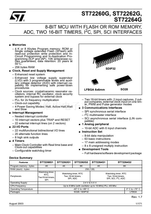
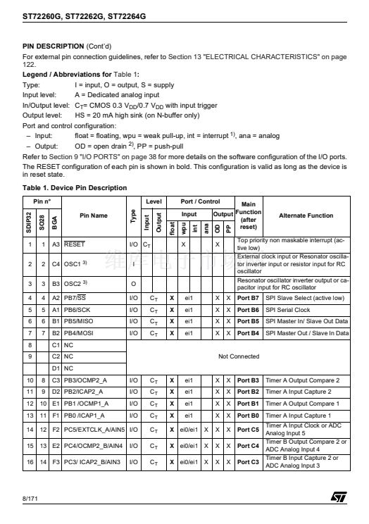
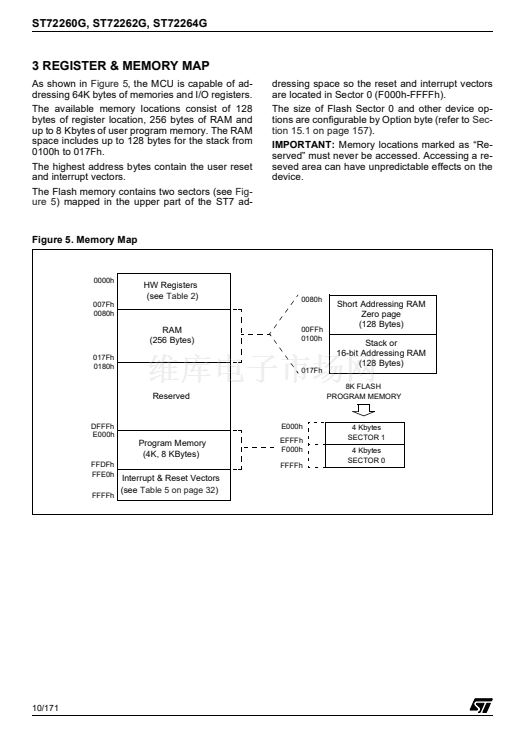
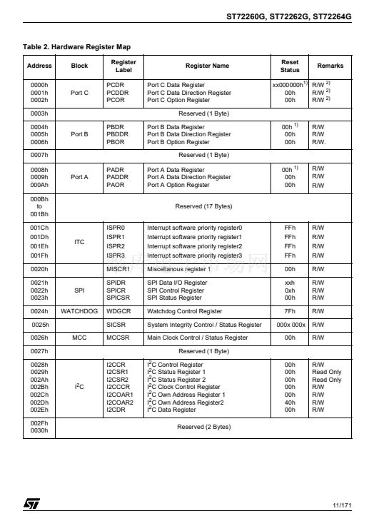
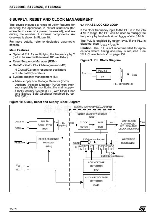
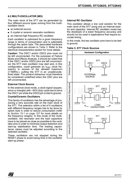
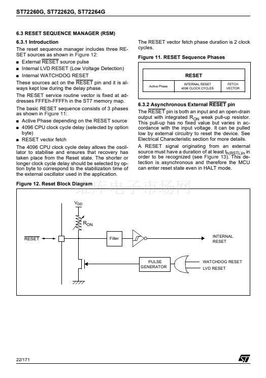
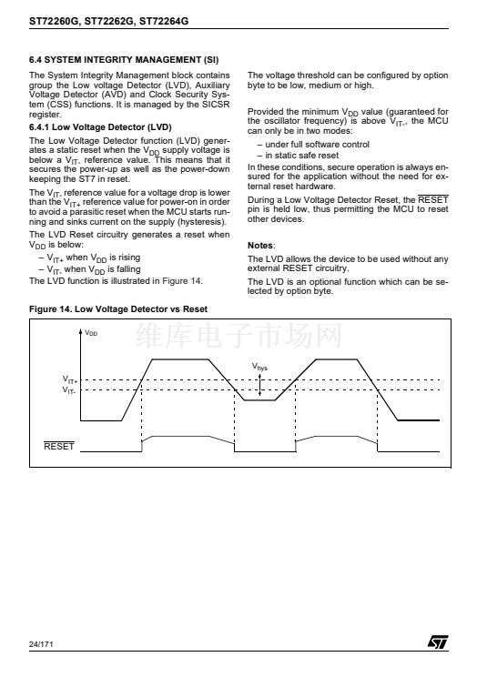
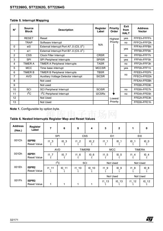
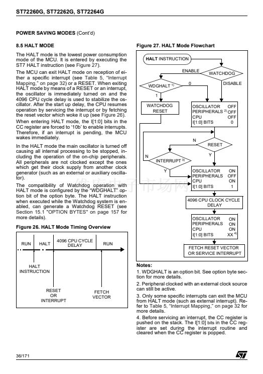
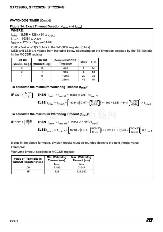
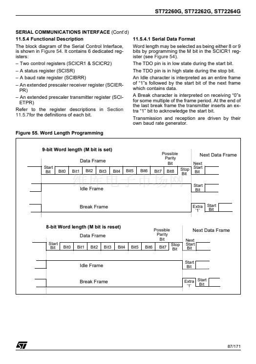
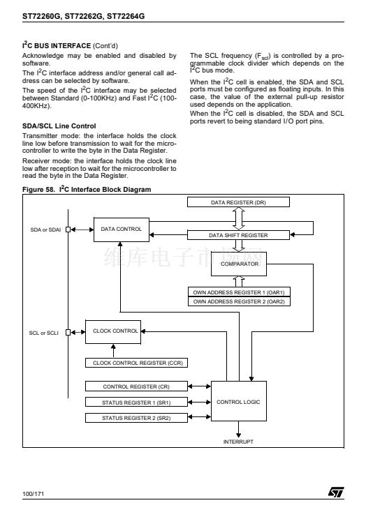
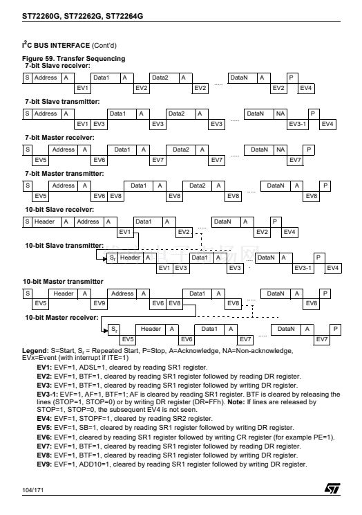
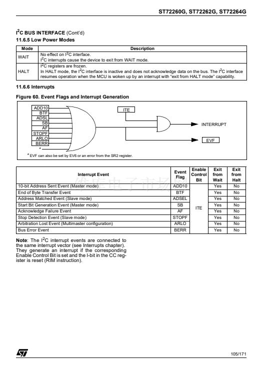
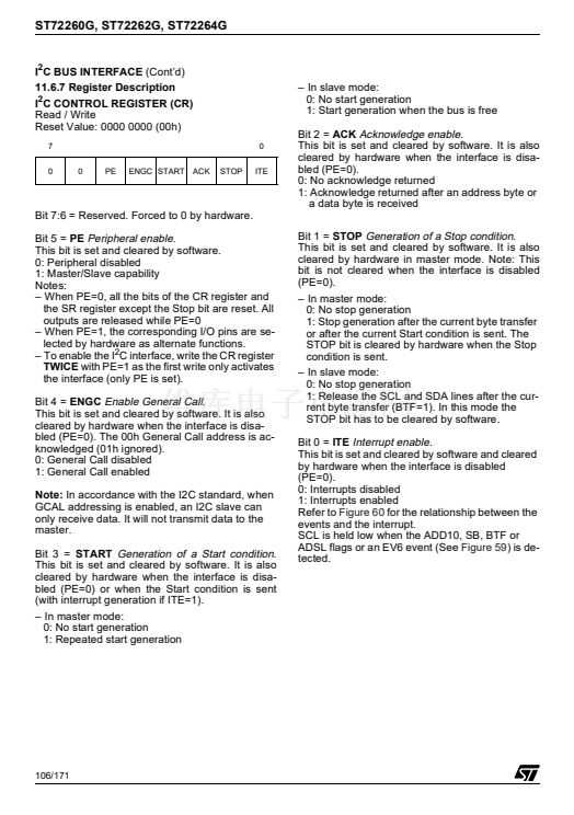
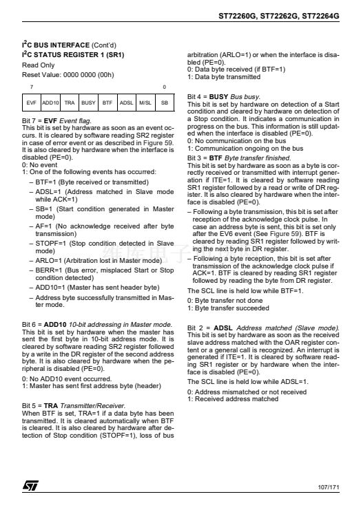
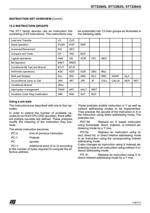
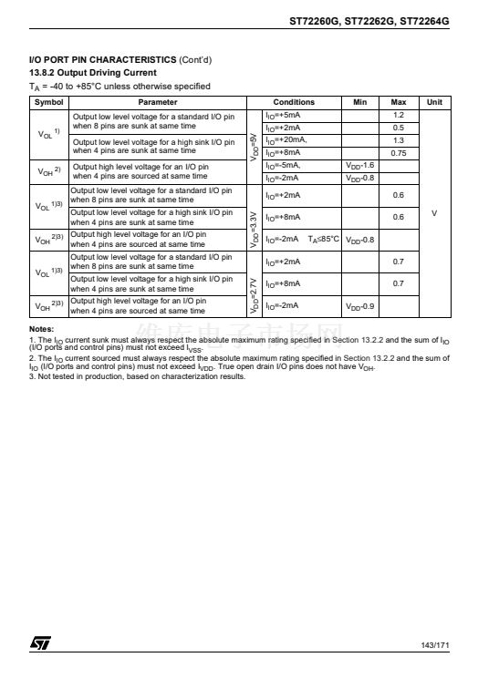
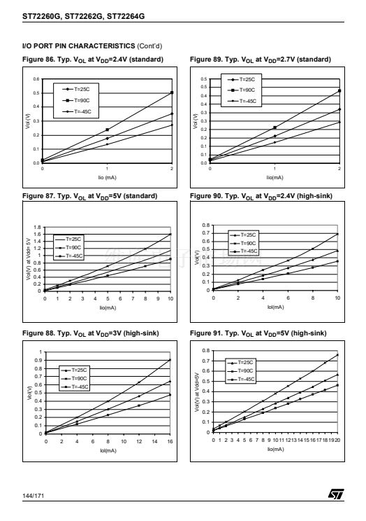
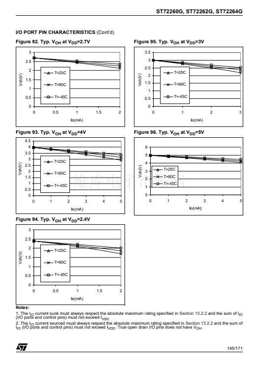
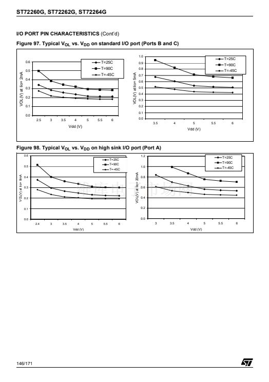
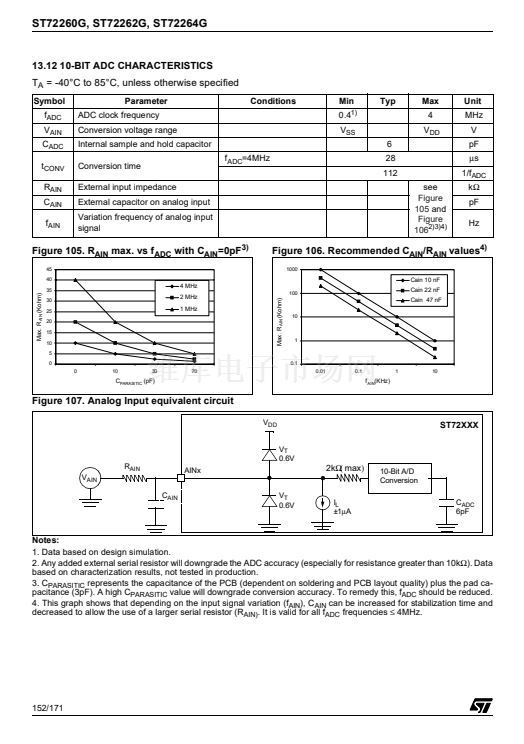
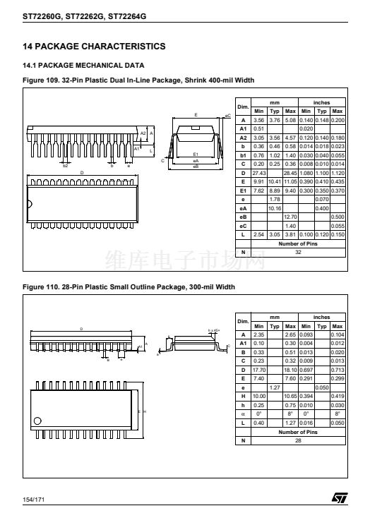
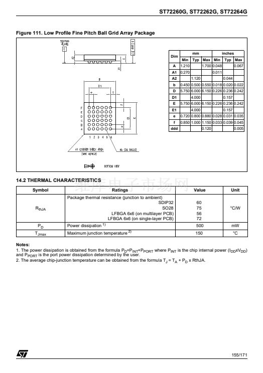
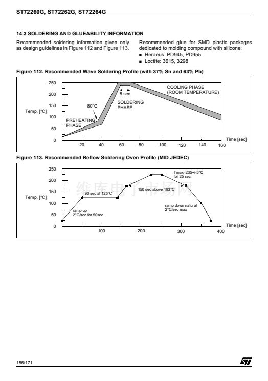
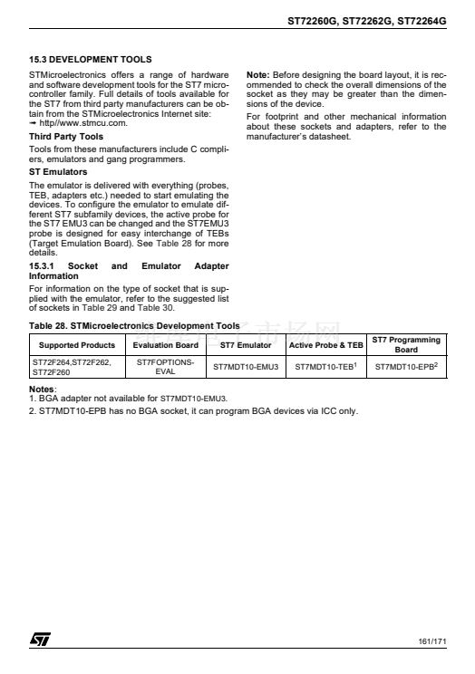
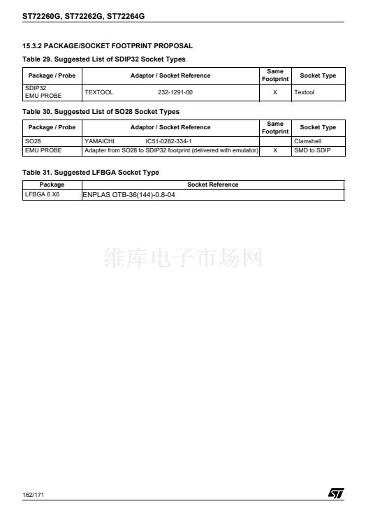
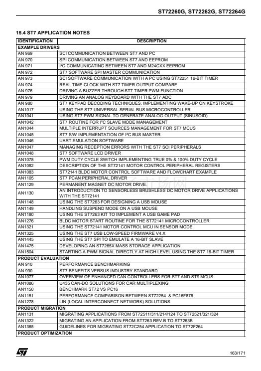
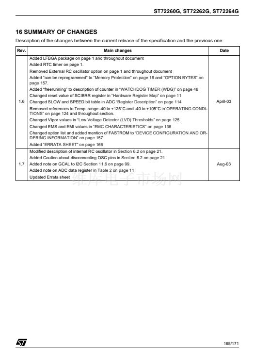
ST72260G, ST72262G, ST72264G
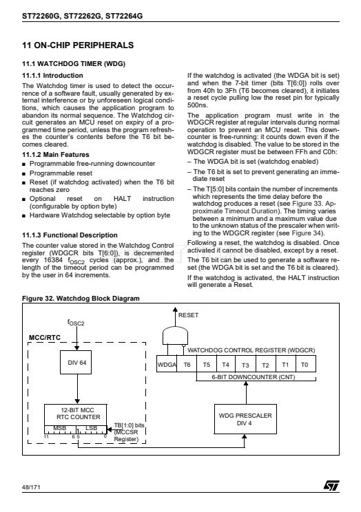
MAIN CLOCK CONTROLLER WITH REAL TIME CLOCK
(Cont鈥檇)
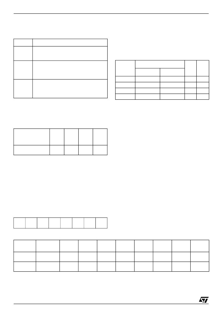
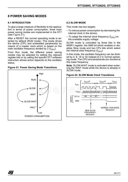
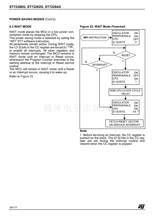
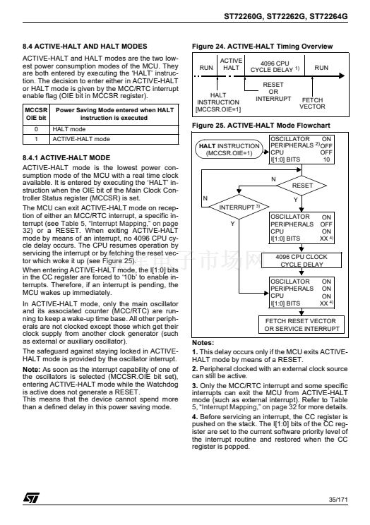
11.2.2 Low Power Modes
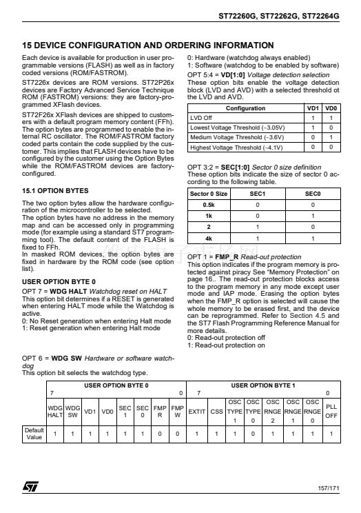
Bit 7:4 =
reserved
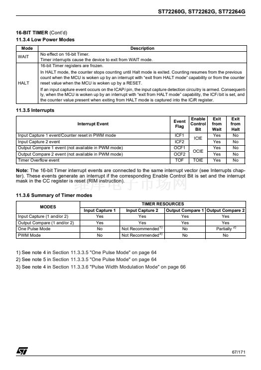
Mode
WAIT
Description
No effect on MCC/RTC peripheral.
MCC/RTC interrupt cause the device to exit
from WAIT mode.
No effect on MCC/RTC counter (OIE bit is
set), the registers are frozen.
MCC/RTC interrupt cause the device to exit
from ACTIVE-HALT mode.
MCC/RTC counter and registers are frozen.
MCC/RTC operation resumes when the
MCU is woken up by an interrupt with 鈥渆xit
from HALT鈥?capability.
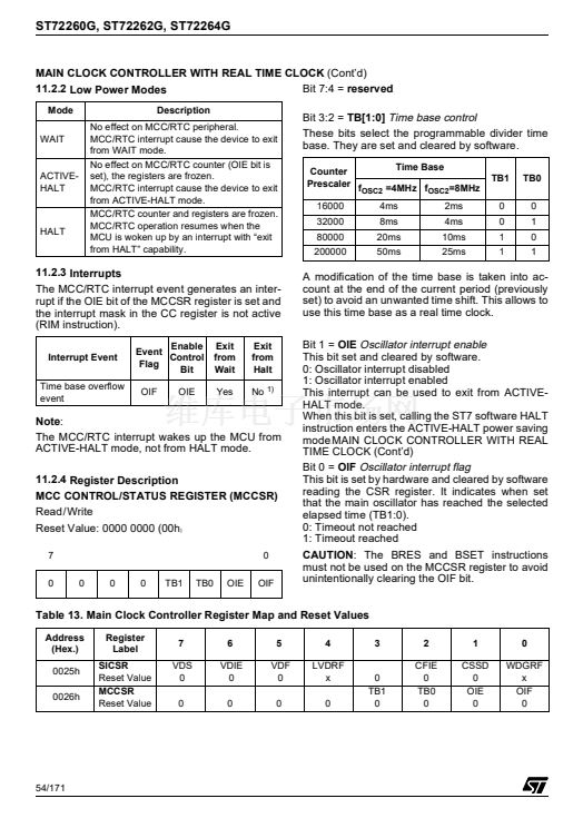
Bit 3:2 =
TB[1:0]
Time base control
These bits select the programmable divider time
base. They are set and cleared by software.
Time Base
Counter
Prescaler f
OSC2
=4MHz f
OSC2
=8MHz
16000
32000
80000
200000
4ms
8ms
20ms
50ms
2ms
4ms
10ms
25ms
TB1
0
0
1
1
TB0
0
1
0
1
ACTIVE-
HALT
HALT
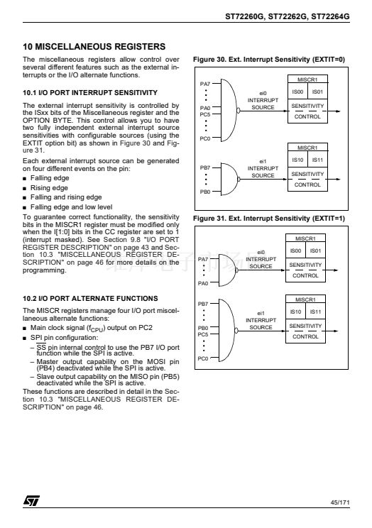
11.2.3 Interrupts
The MCC/RTC interrupt event generates an inter-
rupt if the OIE bit of the MCCSR register is set and
the interrupt mask in the CC register is not active
(RIM instruction).
Interrupt Event
Time base overflow
event
Enable
Event
Control
Flag
Bit
OIF
OIE
Exit
from
Wait
Yes
Exit
from
Halt
No
1)
A modification of the time base is taken into ac-
count at the end of the current period (previously
set) to avoid an unwanted time shift. This allows to
use this time base as a real time clock.
Bit 1 =
OIE
Oscillator interrupt enable
This bit set and cleared by software.
0: Oscillator interrupt disabled
1: Oscillator interrupt enabled
This interrupt can be used to exit from ACTIVE-
HALT mode.
When this bit is set, calling the ST7 software HALT
instruction enters the ACTIVE-HALT power saving
mode
.
MAIN CLOCK CONTROLLER WITH REAL
TIME CLOCK (Cont鈥檇)
Bit 0 =
OIF
Oscillator interrupt flag
This bit is set by hardware and cleared by software
reading the CSR register. It indicates when set
that the main oscillator has reached the selected
elapsed time (TB1:0).
0: Timeout not reached
1: Timeout reached
CAUTION:
The BRES and BSET instructions
must not be used on the MCCSR register to avoid
unintentionally clearing the OIF bit.
Note:
The MCC/RTC interrupt wakes up the MCU from
ACTIVE-HALT mode, not from HALT mode.
11.2.4 Register Description
MCC CONTROL/STATUS REGISTER (MCCSR)
Read /Write
Reset Value: 0000 0000 (00h
)
7
0
0
0
0
TB1
TB0
OIE
0
OIF
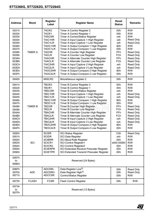
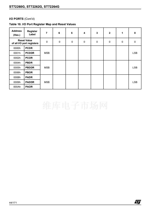
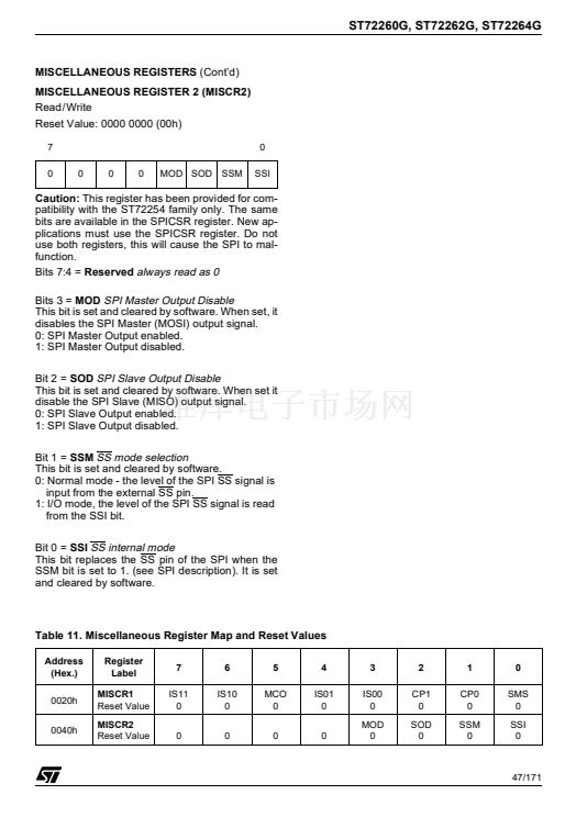
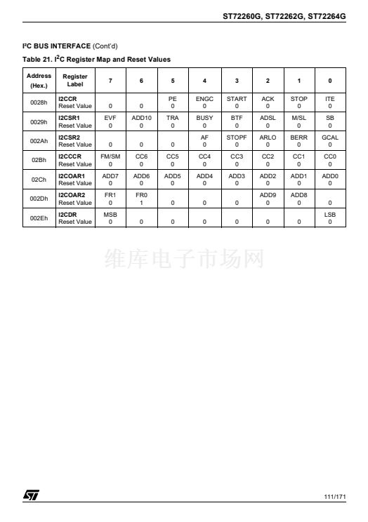
Table 13. Main Clock Controller Register Map and Reset Values
Address
(Hex.)
0025h
0026h
Register
Label
SICSR
Reset Value
MCCSR
Reset Value
7
VDS
0
0
6
VDIE
0
0
5
VDF
0
0
4
LVDRF
x
0
3
2
CFIE
0
TB0
0
1
CSSD
0
OIE
0
0
WDGRF
x
OIF
0
0
TB1
0
54/171


 1
1
 2
2
 3
3
 4
4
 5
5
 6
6
 7
7
 8
8
 9
9
 10
10
 11
11
 12
12
 13
13
 14
14
 15
15
 16
16
 17
17
 18
18
 19
19
 20
20
 21
21
 22
22
 23
23
 24
24
 25
25
 26
26
 27
27
 28
28
 29
29
 30
30
 31
31
 32
32
 33
33
 34
34
 35
35
 36
36
 37
37
 38
38
 39
39
 40
40
 41
41
 42
42
 43
43
 44
44
 45
45
 46
46
 47
47
 48
48
 49
49
 50
50
 51
51
 52
52
 53
53
 54
54
 55
55
 56
56
 57
57
 58
58
 59
59
 60
60
 61
61
 62
62
 63
63
 64
64
 65
65
 66
66
 67
67
 68
68
 69
69
 70
70
 71
71
 72
72
 73
73
 74
74
 75
75
 76
76
 77
77
 78
78
 79
79
 80
80
 81
81
 82
82
 83
83
 84
84
 85
85
 86
86
 87
87
 88
88
 89
89
 90
90
 91
91
 92
92
 93
93
 94
94
 95
95
 96
96
 97
97
 98
98
 99
99
 100
100
 101
101
 102
102
 103
103
 104
104
 105
105
 106
106
 107
107
 108
108
 109
109
 110
110
 111
111
 112
112
 113
113
 114
114
 115
115
 116
116
 117
117
 118
118
 119
119
 120
120
 121
121
 122
122
 123
123
 124
124
 125
125
 126
126
 127
127
 128
128
 129
129
 130
130
 131
131
 132
132
 133
133
 134
134
 135
135
 136
136
 137
137
 138
138
 139
139
 140
140
 141
141
 142
142
 143
143
 144
144
 145
145
 146
146
 147
147
 148
148
 149
149
 150
150
 151
151
 152
152
 153
153
 154
154
 155
155
 156
156
 157
157
 158
158
 159
159
 160
160
 161
161
 162
162
 163
163
 164
164
 165
165
 166
166
 167
167
 168
168
 169
169
 170
170
 171
171
