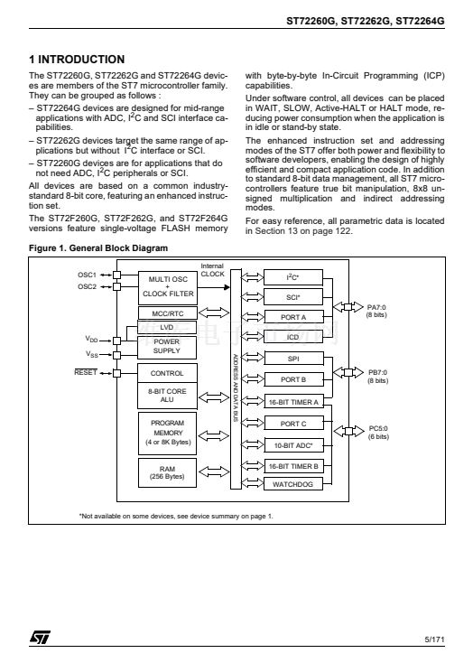
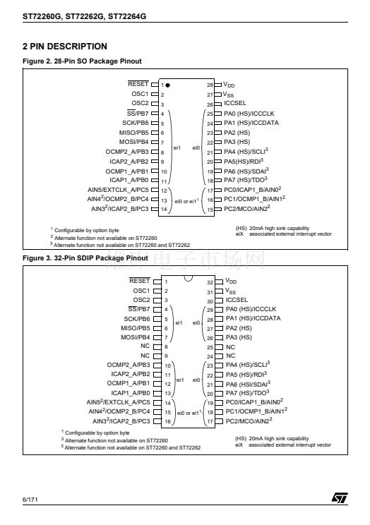
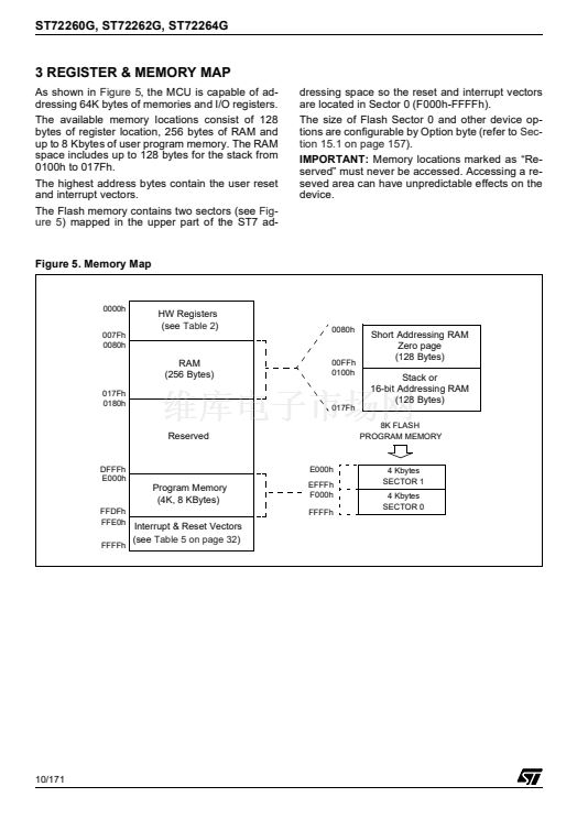
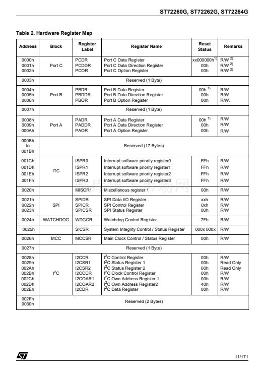
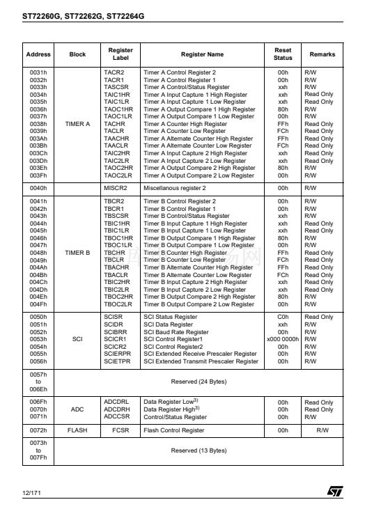
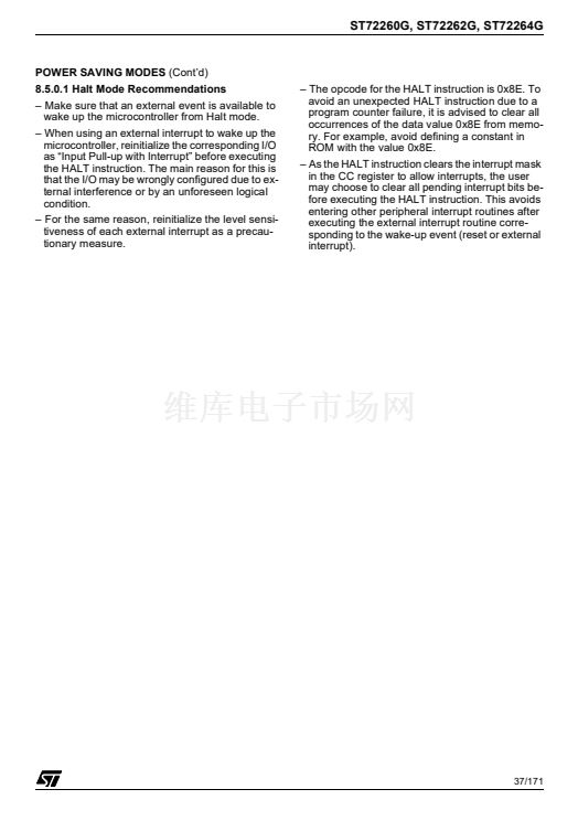
ST72260G, ST72262G, ST72264G
16-BIT TIMER
(Cont鈥檇)
Notes:
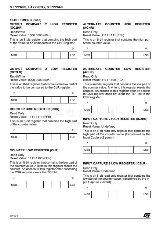
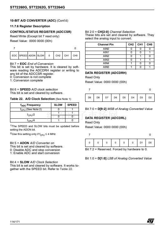
1. After a processor write cycle to the OCiHR reg-
ister, the output compare function is inhibited
until the OCiLR register is also written.
2. If the OCiE bit is not set, the OCMPi pin is a
general I/O port and the OLVLi bit will not
appear when a match is found but an interrupt
could be generated if the OCIE bit is set.
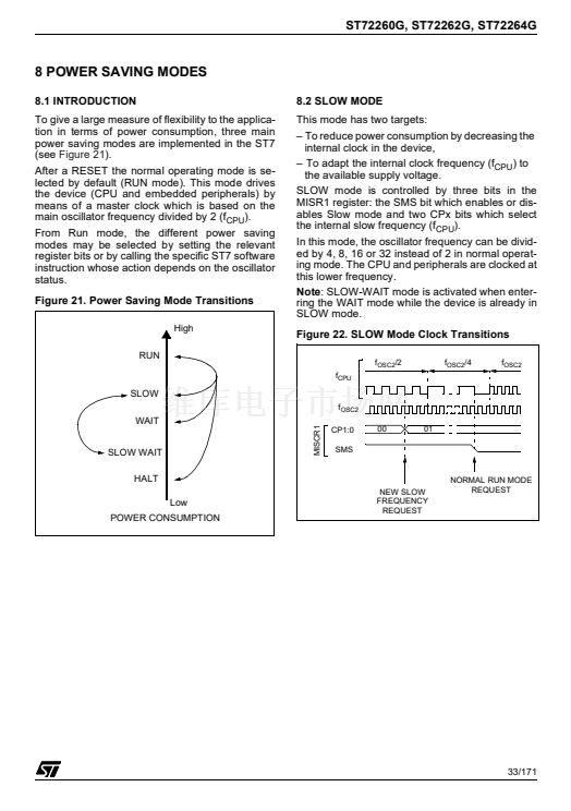
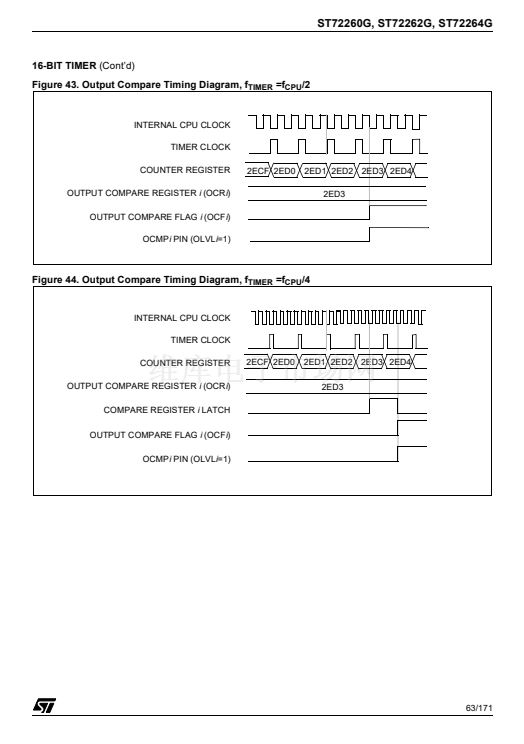
3. When the timer clock is f
CPU
/2, OCFi and
OCMPi are set while the counter value equals
the OCiR register value (see
Figure 43 on page
63).
This behaviour is the same in OPM or
PWM mode.
When the timer clock is f
CPU
/4, f
CPU
/8 or in
external clock mode, OCFi and OCMPi are set
while the counter value equals the OC
iR
regis-
ter value plus 1 (see
Figure 44 on page 63).
4. The output compare functions can be used both
for generating external events on the OCMPi
pins even if the input capture mode is also
used.
5. The value in the 16-bit OC
i
R register and the
OLVi bit should be changed after each suc-
cessful comparison in order to control an output
waveform or establish a new elapsed timeout.
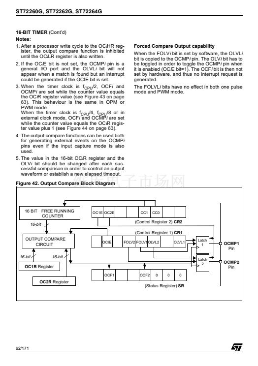
Figure 42. Output Compare Block Diagram
Forced Compare Output capability
When the FOLVi bit is set by software, the OLVLi
bit is copied to the OCMPi pin. The OLVi bit has to
be toggled in order to toggle the OCMPi pin when
it is enabled (OCiE bit=1). The OCFi bit is then not
set by hardware, and thus no interrupt request is
generated.
The FOLVLi bits have no effect in both one pulse
mode and PWM mode.
16 BIT FREE RUNNING
COUNTER
OC1E OC2E
CC1
CC0
16-bit
OUTPUT COMPARE
CIRCUIT
(Control Register 2)
CR2
(Control Register 1)
CR1
OCIE
FOLV2 FOLV1 OLVL2
OLVL1
Latch
1
OCMP1
Pin
OCMP2
Pin
16-bit
16-bit
OC1R
Register
OCF1
OCF2
0
0
0
Latch
2
OC2R
Register
(Status Register)
SR
62/171


 1
1
 2
2
 3
3
 4
4
 5
5
 6
6
 7
7
 8
8
 9
9
 10
10
 11
11
 12
12
 13
13
 14
14
 15
15
 16
16
 17
17
 18
18
 19
19
 20
20
 21
21
 22
22
 23
23
 24
24
 25
25
 26
26
 27
27
 28
28
 29
29
 30
30
 31
31
 32
32
 33
33
 34
34
 35
35
 36
36
 37
37
 38
38
 39
39
 40
40
 41
41
 42
42
 43
43
 44
44
 45
45
 46
46
 47
47
 48
48
 49
49
 50
50
 51
51
 52
52
 53
53
 54
54
 55
55
 56
56
 57
57
 58
58
 59
59
 60
60
 61
61
 62
62
 63
63
 64
64
 65
65
 66
66
 67
67
 68
68
 69
69
 70
70
 71
71
 72
72
 73
73
 74
74
 75
75
 76
76
 77
77
 78
78
 79
79
 80
80
 81
81
 82
82
 83
83
 84
84
 85
85
 86
86
 87
87
 88
88
 89
89
 90
90
 91
91
 92
92
 93
93
 94
94
 95
95
 96
96
 97
97
 98
98
 99
99
 100
100
 101
101
 102
102
 103
103
 104
104
 105
105
 106
106
 107
107
 108
108
 109
109
 110
110
 111
111
 112
112
 113
113
 114
114
 115
115
 116
116
 117
117
 118
118
 119
119
 120
120
 121
121
 122
122
 123
123
 124
124
 125
125
 126
126
 127
127
 128
128
 129
129
 130
130
 131
131
 132
132
 133
133
 134
134
 135
135
 136
136
 137
137
 138
138
 139
139
 140
140
 141
141
 142
142
 143
143
 144
144
 145
145
 146
146
 147
147
 148
148
 149
149
 150
150
 151
151
 152
152
 153
153
 154
154
 155
155
 156
156
 157
157
 158
158
 159
159
 160
160
 161
161
 162
162
 163
163
 164
164
 165
165
 166
166
 167
167
 168
168
 169
169
 170
170
 171
171
