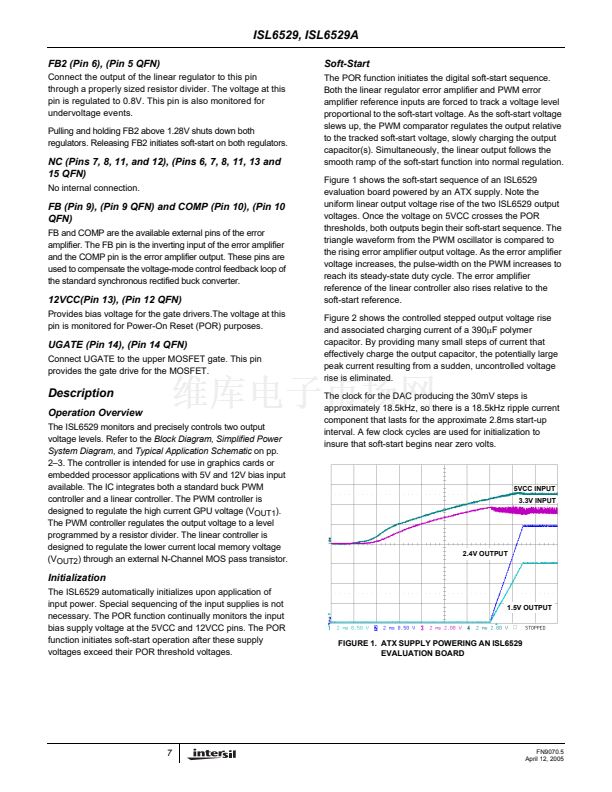
ISL6529, ISL6529A
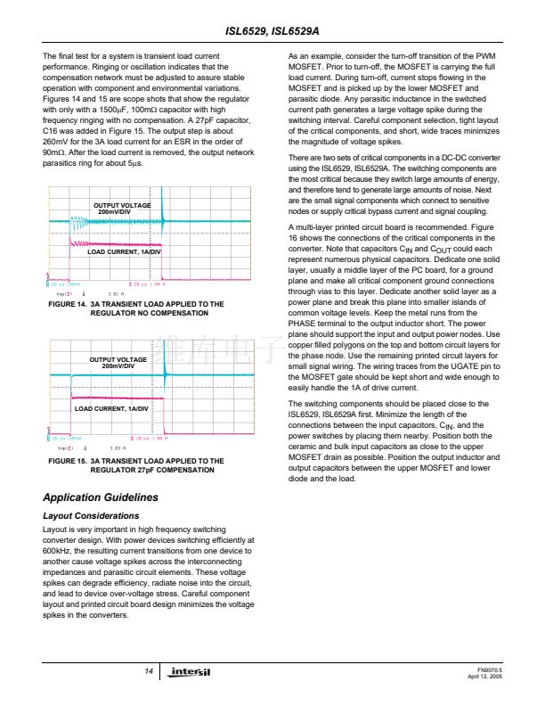
The final test for a system is transient load current
performance. Ringing or oscillation indicates that the
compensation network must be adjusted to assure stable
operation with component and environmental variations.
Figures 14 and 15 are scope shots that show the regulator
with only with a 1500碌F, 100m鈩?capacitor with high
frequency ringing with no compensation. A 27pF capacitor,
C16 was added in Figure 15. The output step is about
260mV for the 3A load current for an ESR in the order of
90m鈩? After the load current is removed, the output network
parasitics ring for about 5碌s.
As an example, consider the turn-off transition of the PWM
MOSFET. Prior to turn-off, the MOSFET is carrying the full
load current. During turn-off, current stops flowing in the
MOSFET and is picked up by the lower MOSFET and
parasitic diode. Any parasitic inductance in the switched
current path generates a large voltage spike during the
switching interval. Careful component selection, tight layout
of the critical components, and short, wide traces minimizes
the magnitude of voltage spikes.
There are two sets of critical components in a DC-DC converter
using the ISL6529, ISL6529A. The switching components are
the most critical because they switch large amounts of energy,
and therefore tend to generate large amounts of noise. Next
are the small signal components which connect to sensitive
nodes or supply critical bypass current and signal coupling.
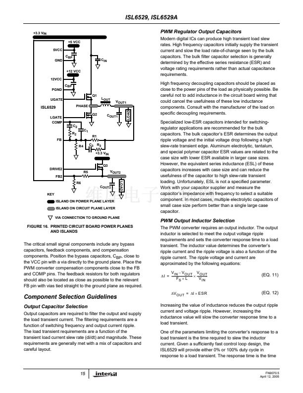
A multi-layer printed circuit board is recommended. Figure
16 shows the connections of the critical components in the
converter. Note that capacitors C
IN
and C
OUT
could each
represent numerous physical capacitors. Dedicate one solid
layer, usually a middle layer of the PC board, for a ground
plane and make all critical component ground connections
through vias to this layer. Dedicate another solid layer as a
power plane and break this plane into smaller islands of
common voltage levels. Keep the metal runs from the
PHASE terminal to the output inductor short. The power
plane should support the input and output power nodes. Use
copper filled polygons on the top and bottom circuit layers for
the phase node. Use the remaining printed circuit layers for
small signal wiring. The wiring traces from the UGATE pin to
the MOSFET gate should be kept short and wide enough to
easily handle the 1A of drive current.
The switching components should be placed close to the
ISL6529, ISL6529A first. Minimize the length of the
connections between the input capacitors, C
IN
, and the
power switches by placing them nearby. Position both the
ceramic and bulk input capacitors as close to the upper
MOSFET drain as possible. Position the output inductor and
output capacitors between the upper MOSFET and lower
diode and the load.
OUTPUT VOLTAGE
200mV/DIV
LOAD CURRENT, 1A/DIV
FIGURE 14. 3A TRANSIENT LOAD APPLIED TO THE
REGULATOR NO COMPENSATION
OUTPUT VOLTAGE
200mV/DIV
LOAD CURRENT, 1A/DIV
FIGURE 15. 3A TRANSIENT LOAD APPLIED TO THE
REGULATOR 27pF COMPENSATION
Application Guidelines
Layout Considerations
Layout is very important in high frequency switching
converter design. With power devices switching efficiently at
600kHz, the resulting current transitions from one device to
another cause voltage spikes across the interconnecting
impedances and parasitic circuit elements. These voltage
spikes can degrade efficiency, radiate noise into the circuit,
and lead to device over-voltage stress. Careful component
layout and printed circuit board design minimizes the voltage
spikes in the converters.
14
FN9070.5
April 12, 2005


 1
1
 2
2
 3
3
 4
4
 5
5
 6
6
 7
7
 8
8
 9
9
 10
10
 11
11
 12
12
 13
13
 14
14
 15
15
 16
16
 17
17
 18
18
 19
19
