ISL6529, ISL6529A
+3.3 V
IN
+5 VCC
5VCC
GND
C
BP
C
IN
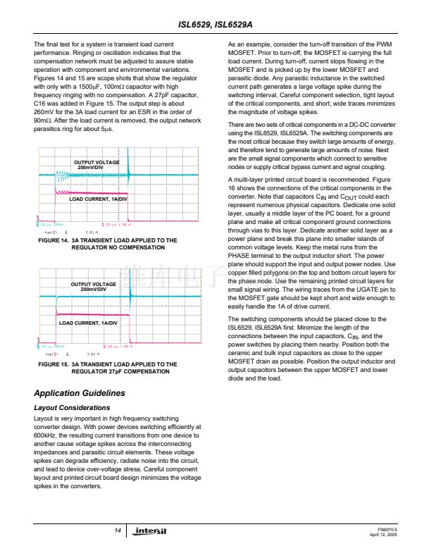
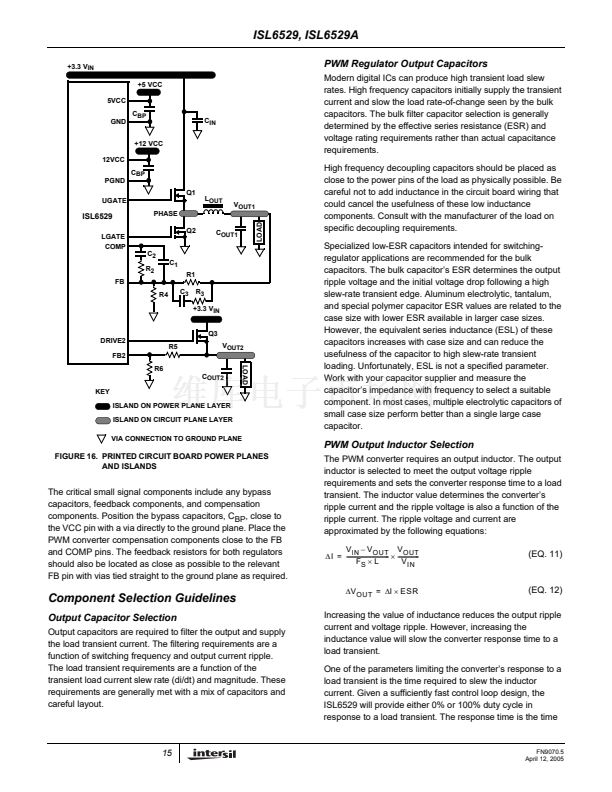
PWM Regulator Output Capacitors
Modern digital ICs can produce high transient load slew
rates. High frequency capacitors initially supply the transient
current and slow the load rate-of-change seen by the bulk
capacitors. The bulk filter capacitor selection is generally
determined by the effective series resistance (ESR) and
voltage rating requirements rather than actual capacitance
requirements.
High frequency decoupling capacitors should be placed as
close to the power pins of the load as physically possible. Be
careful not to add inductance in the circuit board wiring that
could cancel the usefulness of these low inductance
components. Consult with the manufacturer of the load on
specific decoupling requirements.
Specialized low-ESR capacitors intended for switching-
regulator applications are recommended for the bulk
capacitors. The bulk capacitor鈥檚 ESR determines the output
ripple voltage and the initial voltage drop following a high
slew-rate transient edge. Aluminum electrolytic, tantalum,
and special polymer capacitor ESR values are related to the
case size with lower ESR available in larger case sizes.
However, the equivalent series inductance (ESL) of these
capacitors increases with case size and can reduce the
usefulness of the capacitor to high slew-rate transient
loading. Unfortunately, ESL is not a specified parameter.
Work with your capacitor supplier and measure the
capacitor鈥檚 impedance with frequency to select a suitable
component. In most cases, multiple electrolytic capacitors of
small case size perform better than a single large case
capacitor.
+12 VCC
12VCC
PGND
UGATE
C
BP
Q1
L
OUT
V
OUT1
LOAD
LOAD
ISL6529
LGATE
COMP
PHASE
Q2
C
OUT1
C
2
R
2
FB
R4
C
3
R
3
+3.3 V
IN
Q3
R5
R6
C
OUT2
KEY
ISLAND ON POWER PLANE LAYER
ISLAND ON CIRCUIT PLANE LAYER
VIA CONNECTION TO GROUND PLANE
V
OUT2
C
1
R1
DRIVE2
FB2
PWM Output Inductor Selection
The PWM converter requires an output inductor. The output
inductor is selected to meet the output voltage ripple
requirements and sets the converter response time to a load
transient. The inductor value determines the converter鈥檚
ripple current and the ripple voltage is also a function of the
ripple current. The ripple voltage and current are
approximated by the following equations:
V
IN
鈥?/div>
V
OUT
V
OUT
-
-
鈭咺
= -------------------------------
脳
---------------
V
IN
F
S
脳
L
鈭?/div>
V
OUT
=
鈭?/div>
I
脳
ESR
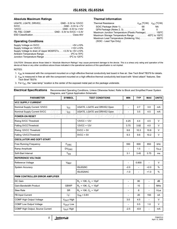
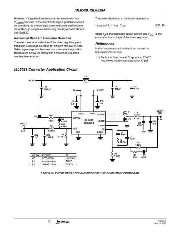
FIGURE 16. PRINTED CIRCUIT BOARD POWER PLANES
AND ISLANDS
The critical small signal components include any bypass
capacitors, feedback components, and compensation
components. Position the bypass capacitors, C
BP
, close to
the VCC pin with a via directly to the ground plane. Place the
PWM converter compensation components close to the FB
and COMP pins. The feedback resistors for both regulators
should also be located as close as possible to the relevant
FB pin with vias tied straight to the ground plane as required.
(EQ. 11)
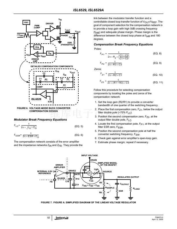
Component Selection Guidelines
Output Capacitor Selection
Output capacitors are required to filter the output and supply
the load transient current. The filtering requirements are a
function of switching frequency and output current ripple.
The load transient requirements are a function of the
transient load current slew rate (di/dt) and magnitude. These
requirements are generally met with a mix of capacitors and
careful layout.
(EQ. 12)
Increasing the value of inductance reduces the output ripple
current and voltage ripple. However, increasing the
inductance value will slow the converter response time to a
load transient.
One of the parameters limiting the converter鈥檚 response to a
load transient is the time required to slew the inductor
current. Given a sufficiently fast control loop design, the
ISL6529 will provide either 0% or 100% duty cycle in
response to a load transient. The response time is the time
15
FN9070.5
April 12, 2005


 1
1
 2
2
 3
3
 4
4
 5
5
 6
6
 7
7
 8
8
 9
9
 10
10
 11
11
 12
12
 13
13
 14
14
 15
15
 16
16
 17
17
 18
18
 19
19
