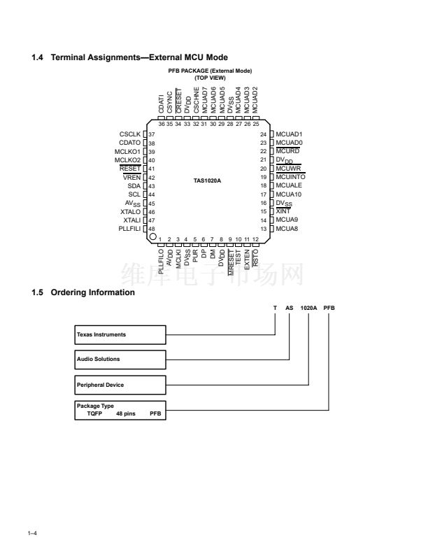
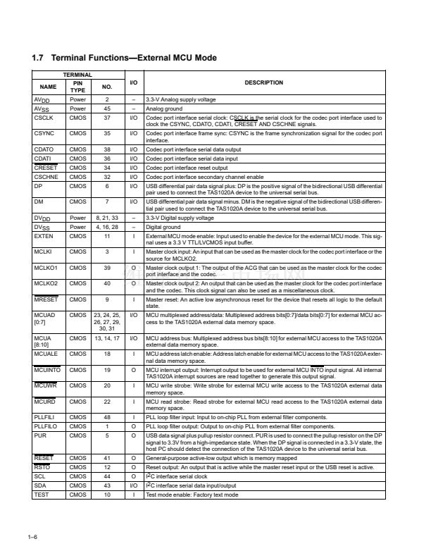
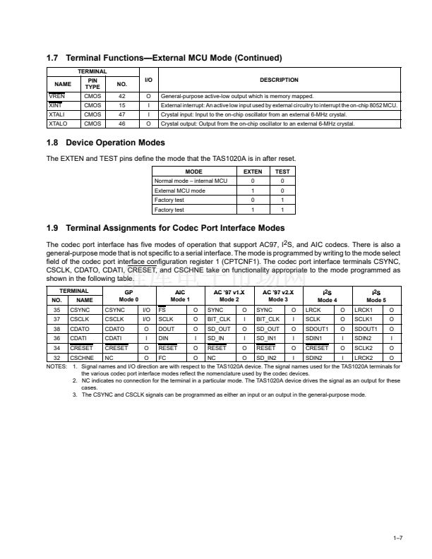
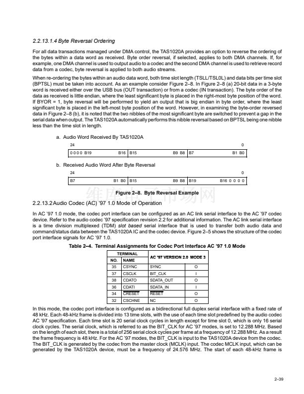
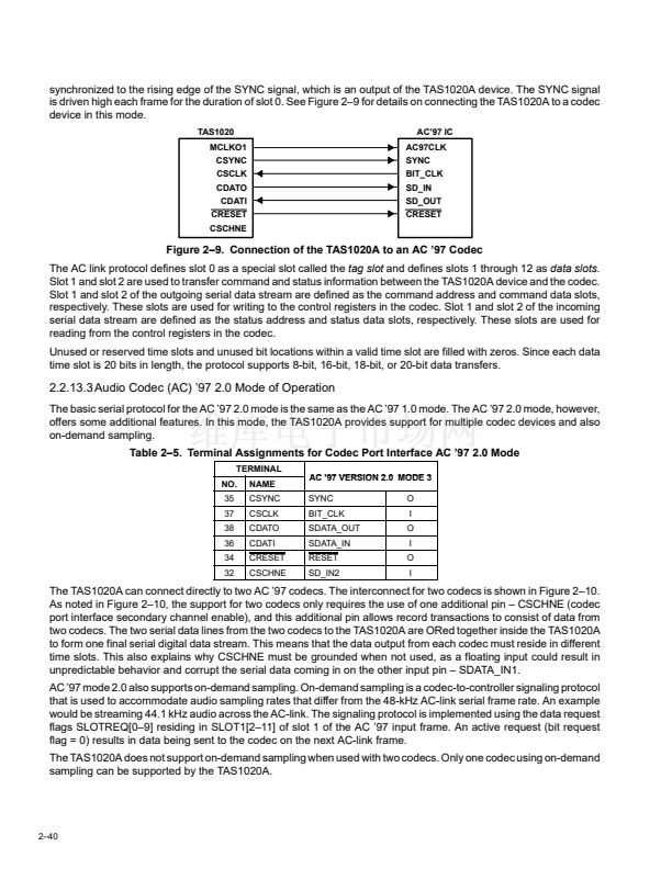
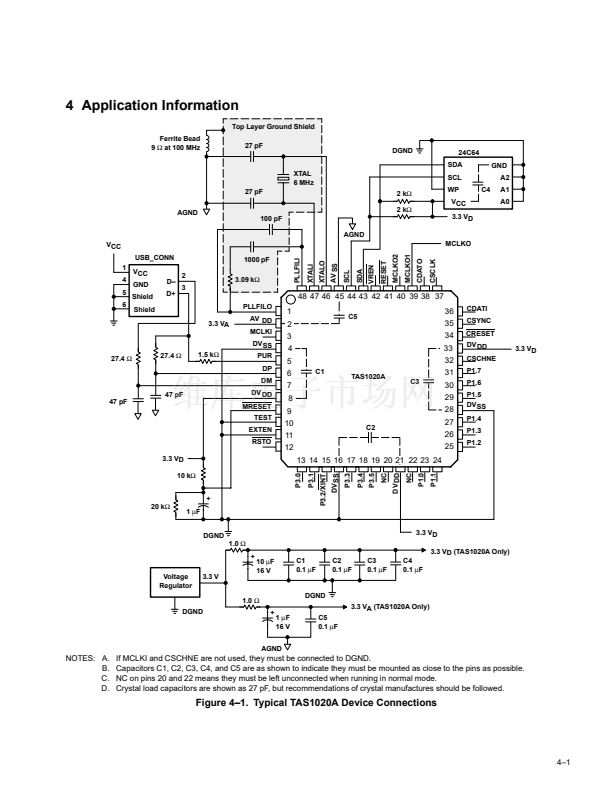
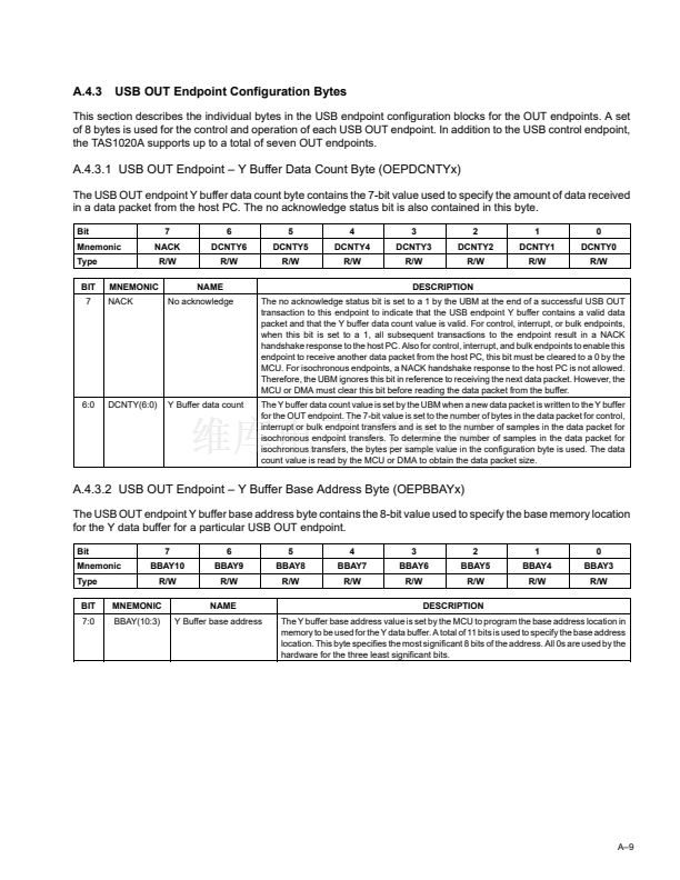
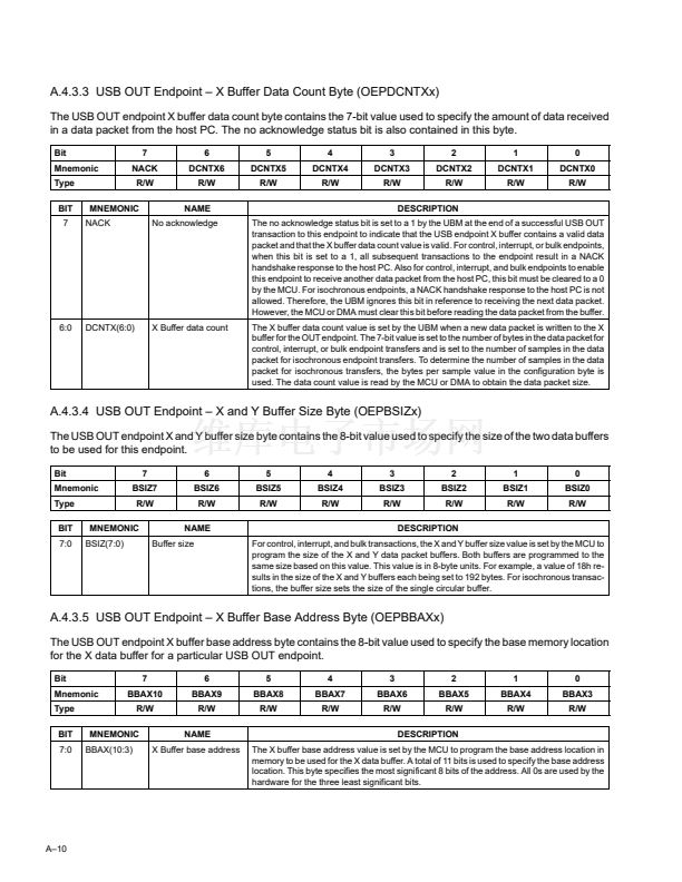
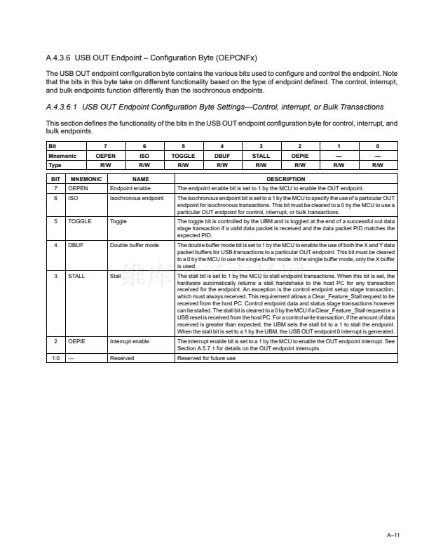
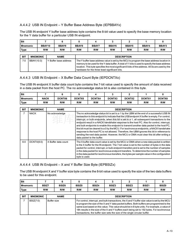
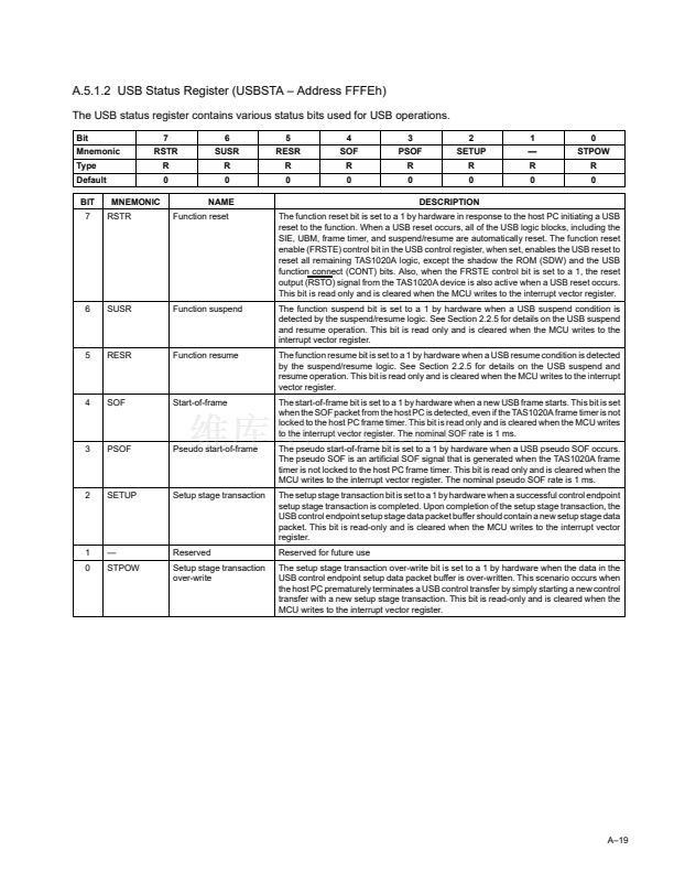
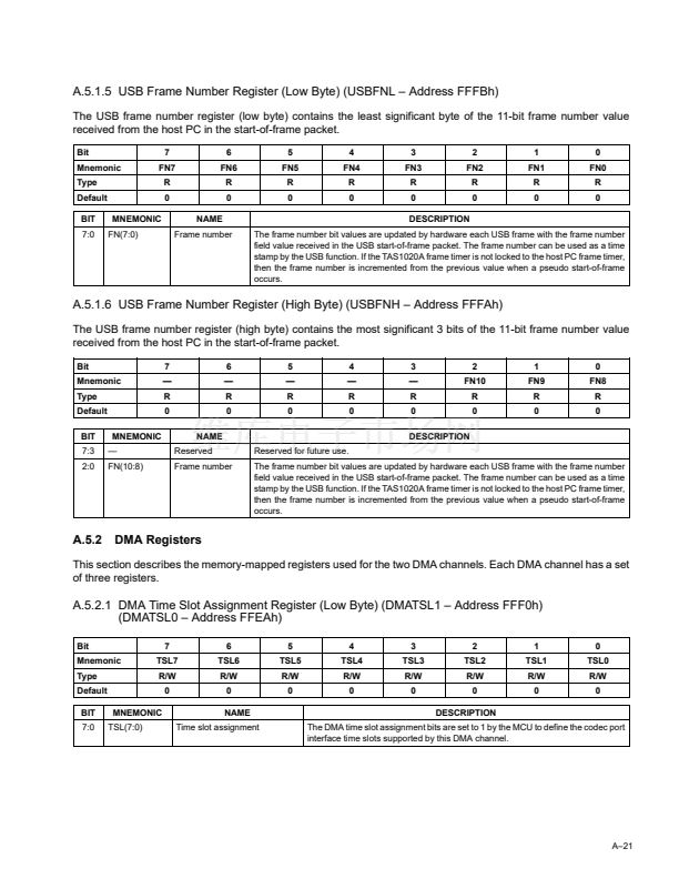
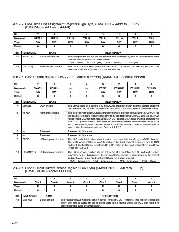
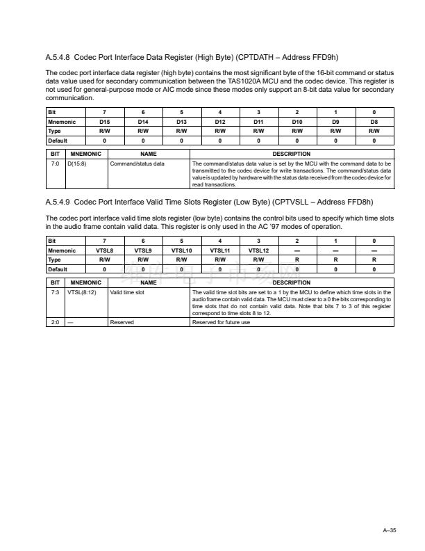
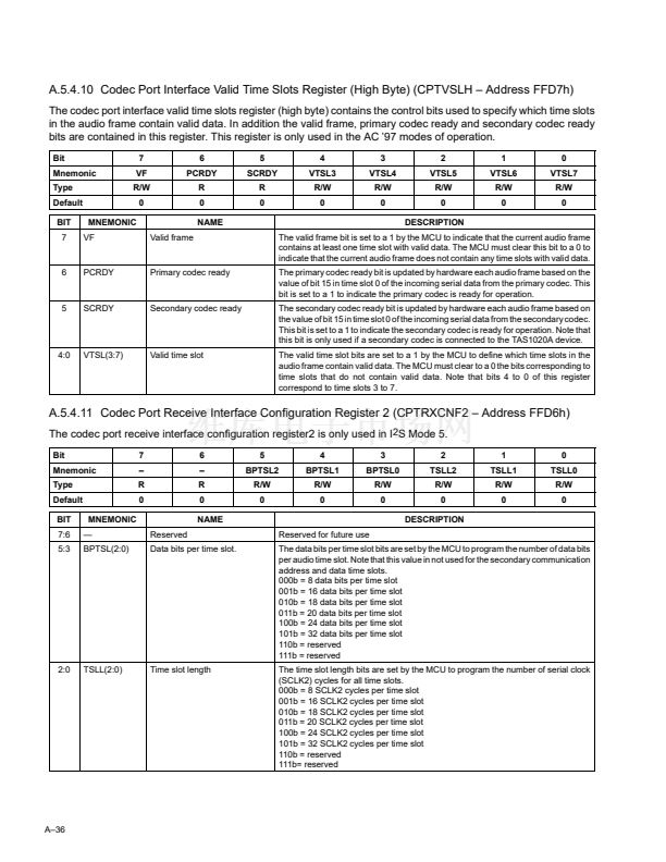
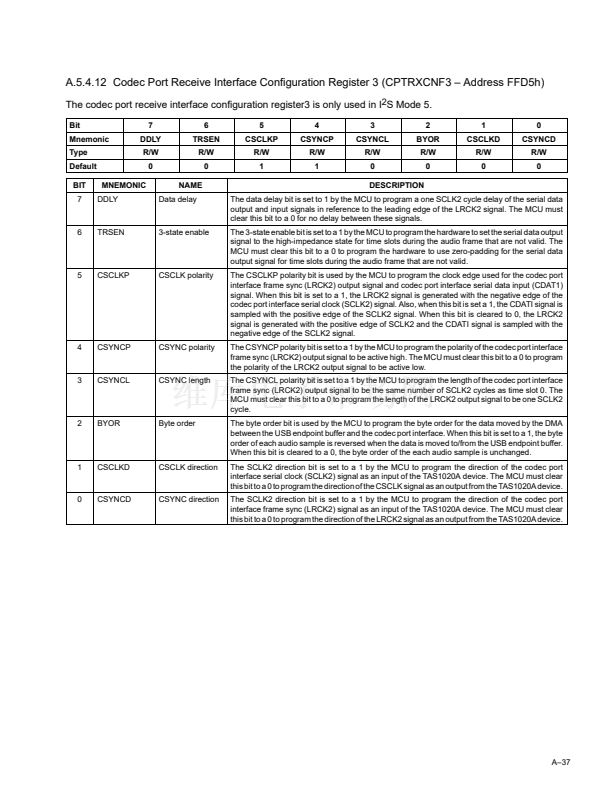
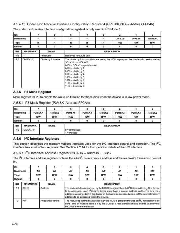
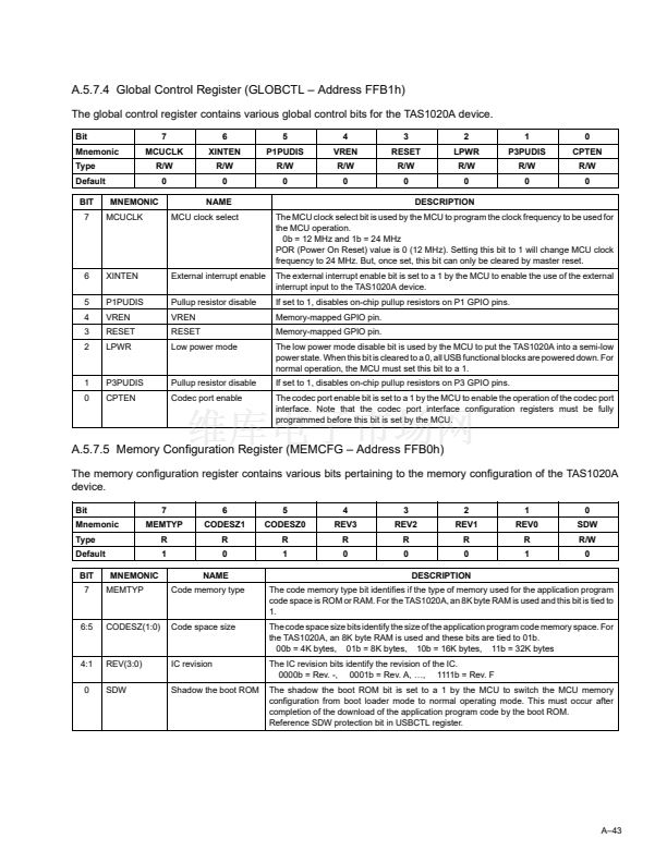
鈥?/div>
2.2.3
USB Enumeration
USB enumeration is accomplished by interaction between the host PC and the TAS1020A. As described in Section
2.2.2, the TAS1020A can identify itself as an application device by reporting its application Vendor ID and Product
ID, or it can identify itself as a DFU device by reporting a Vendor ID of 0xFFFF and a Product ID of 0xFFFE. If the
TAS1020A fails to detect the presence of an EEPROM, or if an EEPROM is present but does not contain a valid
header, the Vendor ID of 0xFFFF and Product ID of 0xFFFE are reported. If an EEPROM is present, but contains
only valid header data, the Vendor ID and Product ID settings in the EEPROM header are reported, but the TAS1020A
firmware comes up as a DFU device in the DFU program mode. If an EEPROM is present, and contains both a valid
header and application code, the TAS1020A comes up as an application specific device.
For all cases where the TAS1020A comes up in the DFU program mode, once application code has been
downloaded, the TAS1020A is reset by a host-issued USB reset. After this reset, the TAS1020A comes up as an
application device. When the TAS1020A comes up as an application device, the ROM-resident boot loader retrieves
the application code from the EEPROM, if the EEPROM is not a device EEPROM, and then runs the application code.
It is the application code that connects the TAS1020A to the USB. During the enumeration that follows connection
to the USB, the application code identifies the device as an application specific device and the host loads the
appropriate host driver(s).
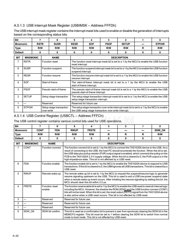
The boot loader and application code both use the CONT, SDW and FRSTE bits to control the enumeration process.
鈥?/div>
The function connect (CONT) bit is set to a 1 by the MCU to connect the TAS1020A device to the USB. When
this bit is set to a 1, the USB DP line pullup resistor (PUR) output signal is enabled. Enabling PUR connects
the pullup on the PCB to the TAS1020A 3.3-V digital supply voltage. (When the TAS1020A powers up, this
bit is cleared to a 0 and the PUR output is in the high-impedance state.) This bit is not affected by subsequent
USB resets.
鈥?/div>
鈥?/div>
The shadow the boot ROM (SDW) bit is set to 1 by the MCU to switch the MCU memory configuration from
boot loader mode to normal operating mode. Once set to 1, this bit is not affected by subsequent USB resets.
The function reset enable (FRSTE) bit is set to a 1 by the MCU to enable the USB reset to reset all internal
logic including the MCU. However, the shadow the ROM (SDW) and the USB function connect (CONT) bits
are not reset. In addition, when the FRSTE bit is set, the reset output (RSTO) signal from the TAS1020A
device is active whenever a USB reset occurs. This bit, once set, is not affected by subsequent USB resets.
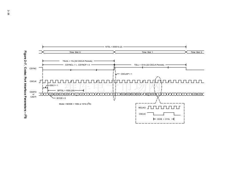
2鈥?


 1
1
 2
2
 3
3
 4
4
 5
5
 6
6
 7
7
 8
8
 9
9
 10
10
 11
11
 12
12
 13
13
 14
14
 15
15
 16
16
 17
17
 18
18
 19
19
 20
20
 21
21
 22
22
 23
23
 24
24
 25
25
 26
26
 27
27
 28
28
 29
29
 30
30
 31
31
 32
32
 33
33
 34
34
 35
35
 36
36
 37
37
 38
38
 39
39
 40
40
 41
41
 42
42
 43
43
 44
44
 45
45
 46
46
 47
47
 48
48
 49
49
 50
50
 51
51
 52
52
 53
53
 54
54
 55
55
 56
56
 57
57
 58
58
 59
59
 60
60
 61
61
 62
62
 63
63
 64
64
 65
65
 66
66
 67
67
 68
68
 69
69
 70
70
 71
71
 72
72
 73
73
 74
74
 75
75
 76
76
 77
77
 78
78
 79
79
 80
80
 81
81
 82
82
 83
83
 84
84
 85
85
 86
86
 87
87
 88
88
 89
89
 90
90
 91
91
 92
92
 93
93
 94
94
 95
95
 96
96
 97
97
 98
98
 99
99
 100
100
 101
101
 102
102
 103
103
 104
104
 105
105
 106
106
 107
107
 108
108
 109
109
 110
110
 111
111
 112
112
 113
113
 114
114
