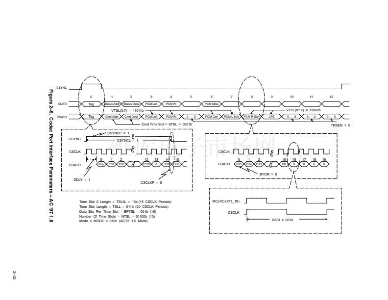
2.2.7
USB Transfers
The TAS1020A device supports all USB data transfer types: control, bulk, interrupt, and isochronous. In accordance
with the USB specification, endpoint zero is reserved for the control endpoint and is bidirectional. In addition to the
control endpoint, the TAS1020A is capable of supporting up to 7 IN endpoints and 7 OUT endpoints. These additional
endpoints can be configured as bulk, interrupt, or isochronous endpoints.
2.2.7.1 Control Transfers
Control transfers are used for configuration, command, and status communication between the host PC and the
TAS1020A device. Control transfers to the TAS1020A device use IN endpoint 0 and OUT endpoint 0. The three types
of control transfers are control write, control write with no data stage, and control reads.
2.2.7.1.1 Control Write Transfer (Out Transfer)
The host PC uses a control write transfer to write data to the USB function. A control write transfer always consists
of a setup stage transaction and an IN status stage, and can optionally contain one or more data stage transactions
between the setup and status transactions. If the data to be transferred can be contained in the two byte value field
of the setup transaction data packet, no data stage transaction is required. If the control information requires the
transfer of more than two bytes of data, a control write transfer with data stage transactions will be required. The steps
followed for a control write transfer are:
Initialization Stage:
1. MCU initializes IN endpoint 0 and OUT endpoint 0 by programming the appropriate USB endpoint
configuration blocks. This entails programming the buffer size and buffer base address, selecting the buffer
mode, enabling the endpoint interrupt, initializing the TOGGLE bit, enabling the endpoint, and clearing the
NACK bit for both IN endpoint 0 and OUT endpoint 0.
Setup Stage Transaction:
1. The host PC sends a setup token followed by the setup data packet addressed to OUT endpoint 0. If the
data is received without an error, the USB Buffer Manager (UBM) writes the data to the setup data packet
buffer, sets the setup stage transaction (SETUP) bit to a 1 in the USB status register, returns an ACK
handshake to the host PC, and asserts the setup stage transaction interrupt. Note that as long as the setup
stage transaction (SETUP) bit is set to a 1, the UBM returns a NACK handshake for any data stage or status
stage transactions regardless of the endpoint 0 NACK or STALL bit values.
2. The MCU services the interrupt, reads the setup data packet from the buffer, and decodes the command.
If the command is not supported or valid, the MCU should set the STALL bit in the OUT endpoint 0
configuration byte and the IN endpoint 0 configuration byte before clearing the setup stage transaction
(SETUP) bit. This causes the device to return a STALL handshake for any data stage or status stage
transactions. If the command decoded is supported, the MCU clears the interrupt, which automatically
clears the setup stage transaction bit. The MCU also sets the TOGGLE bit in the OUT endpoint 0
configuration byte to a 1. For control write transfers, the PID used by the host for the first OUT data packet
is a DATA1 PID and the TOGGLE bit must match.
Optional Data Stage Transaction:
1. The host PC sends an out token packet followed by a data packet addressed to OUT endpoint 0. If the data
packet is received without errors the UBM writes the data to the endpoint buffer, updates the data count
value, toggles the TOGGLE bit, sets the NACK bit to a 1, returns an ACK handshake to the host PC, and
asserts the endpoint interrupt.
2. The MCU services the interrupt and reads the data packet from the buffer. To read the data packet, the MCU
first must obtain the data count value. After reading the data packet, the MCU must clear the interrupt and
clear the NACK bit to allow the reception of the next data packet from the host PC.
2鈥?4


 1
1
 2
2
 3
3
 4
4
 5
5
 6
6
 7
7
 8
8
 9
9
 10
10
 11
11
 12
12
 13
13
 14
14
 15
15
 16
16
 17
17
 18
18
 19
19
 20
20
 21
21
 22
22
 23
23
 24
24
 25
25
 26
26
 27
27
 28
28
 29
29
 30
30
 31
31
 32
32
 33
33
 34
34
 35
35
 36
36
 37
37
 38
38
 39
39
 40
40
 41
41
 42
42
 43
43
 44
44
 45
45
 46
46
 47
47
 48
48
 49
49
 50
50
 51
51
 52
52
 53
53
 54
54
 55
55
 56
56
 57
57
 58
58
 59
59
 60
60
 61
61
 62
62
 63
63
 64
64
 65
65
 66
66
 67
67
 68
68
 69
69
 70
70
 71
71
 72
72
 73
73
 74
74
 75
75
 76
76
 77
77
 78
78
 79
79
 80
80
 81
81
 82
82
 83
83
 84
84
 85
85
 86
86
 87
87
 88
88
 89
89
 90
90
 91
91
 92
92
 93
93
 94
94
 95
95
 96
96
 97
97
 98
98
 99
99
 100
100
 101
101
 102
102
 103
103
 104
104
 105
105
 106
106
 107
107
 108
108
 109
109
 110
110
 111
111
 112
112
 113
113
 114
114
