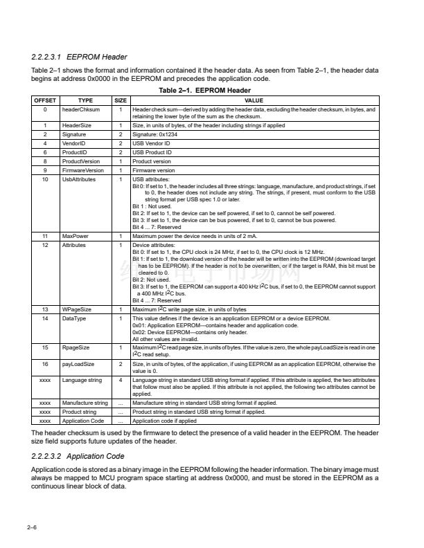
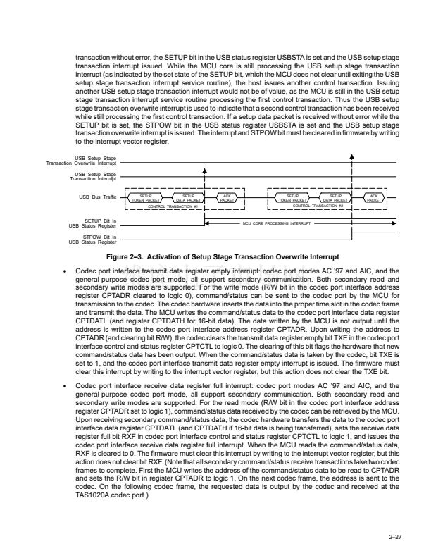
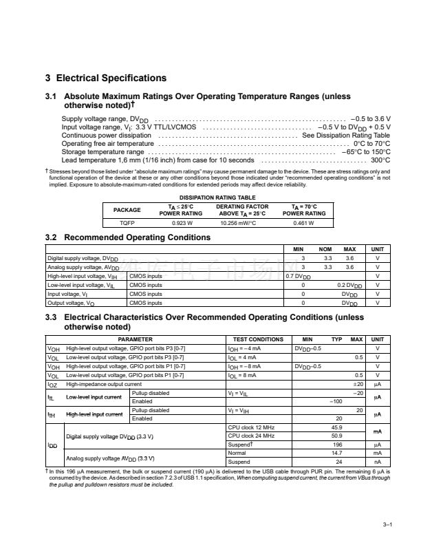
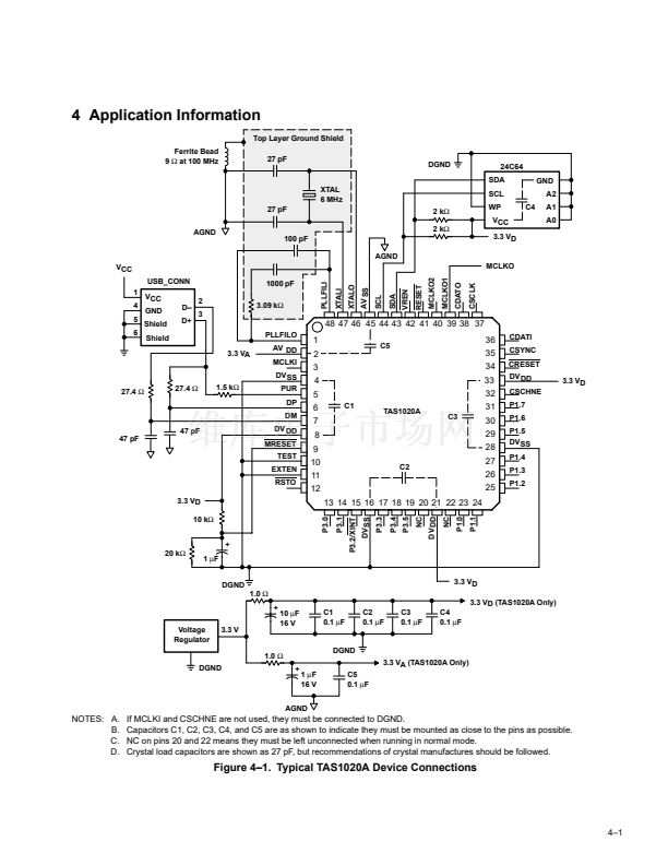
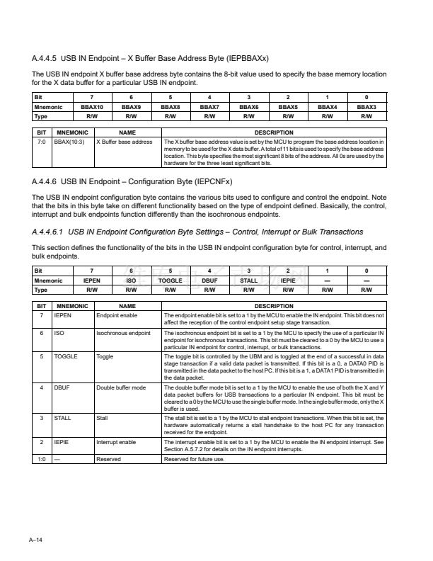
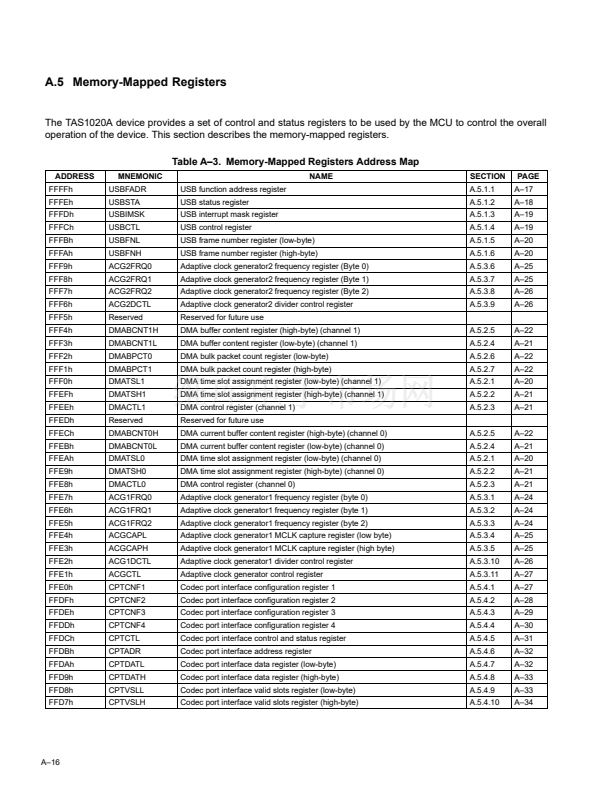
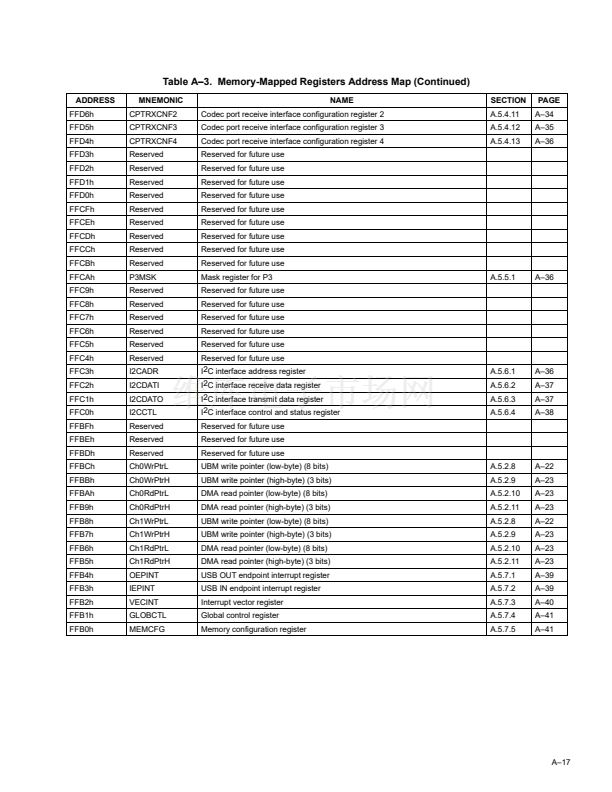
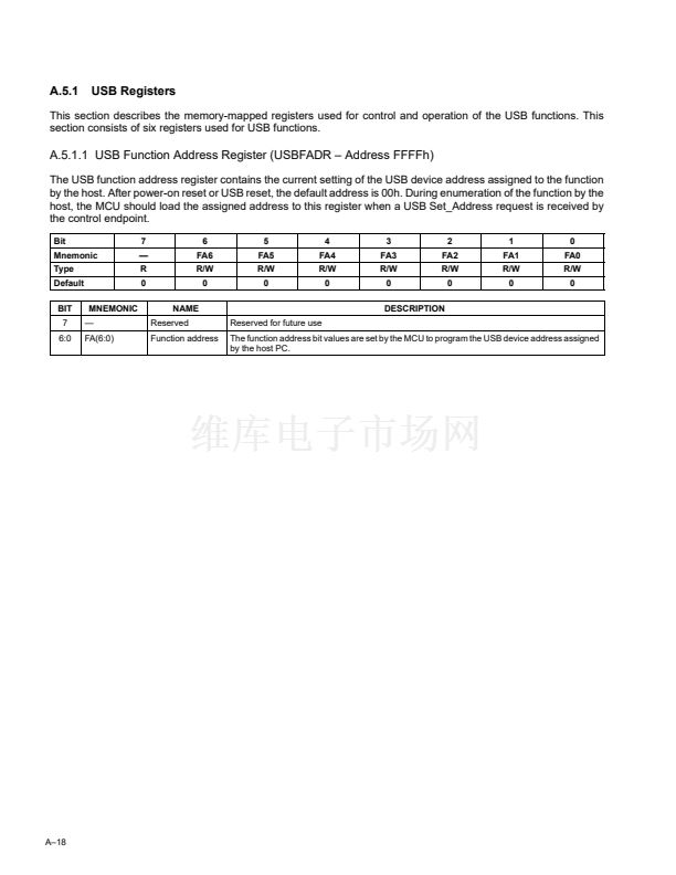
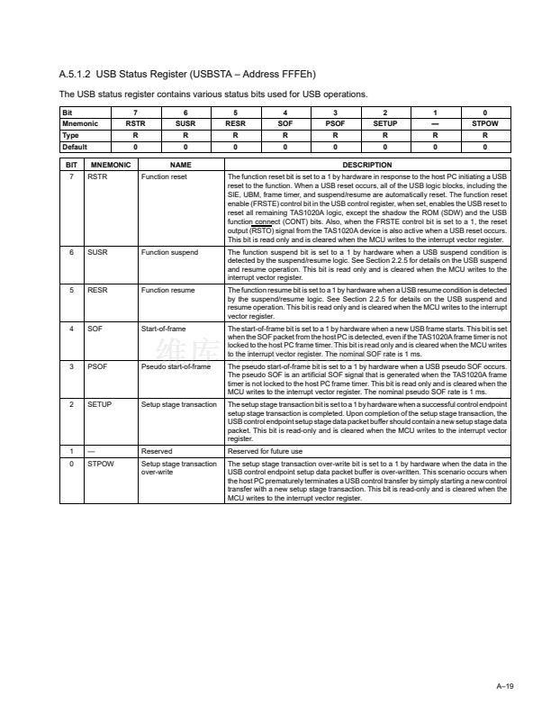
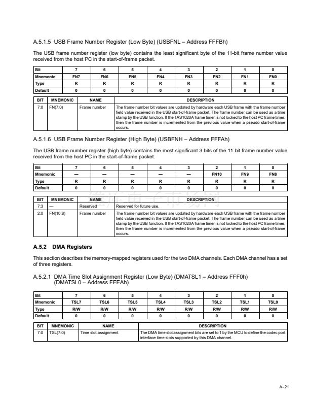
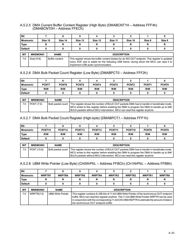
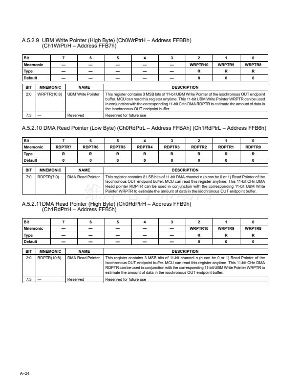
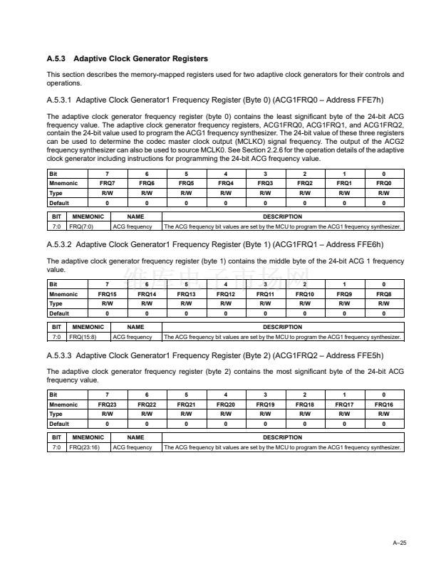
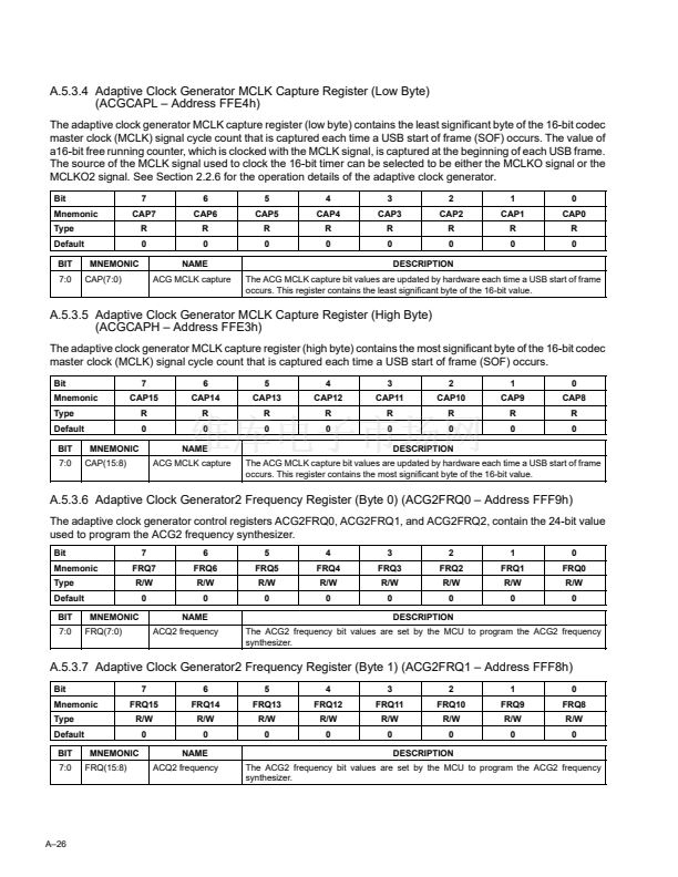
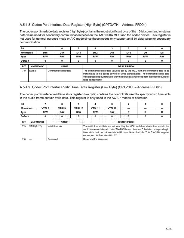
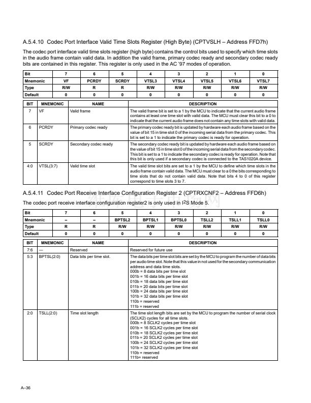
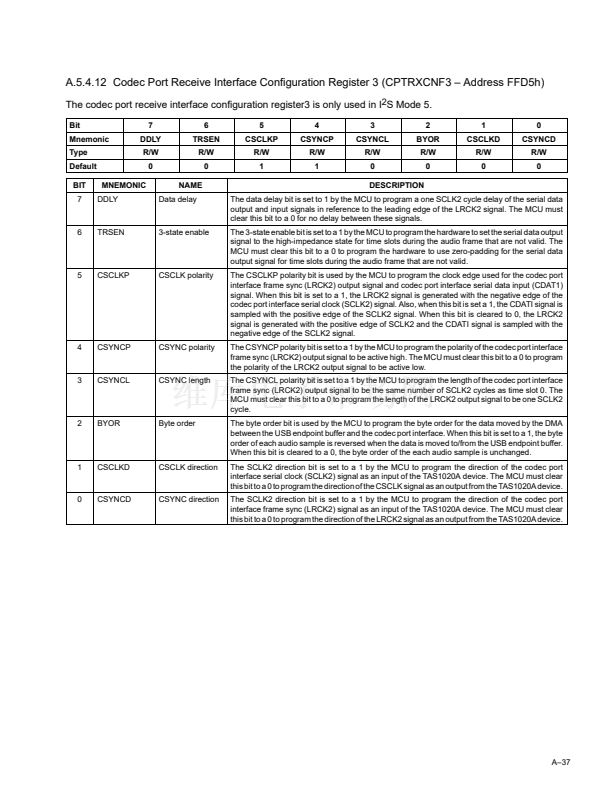
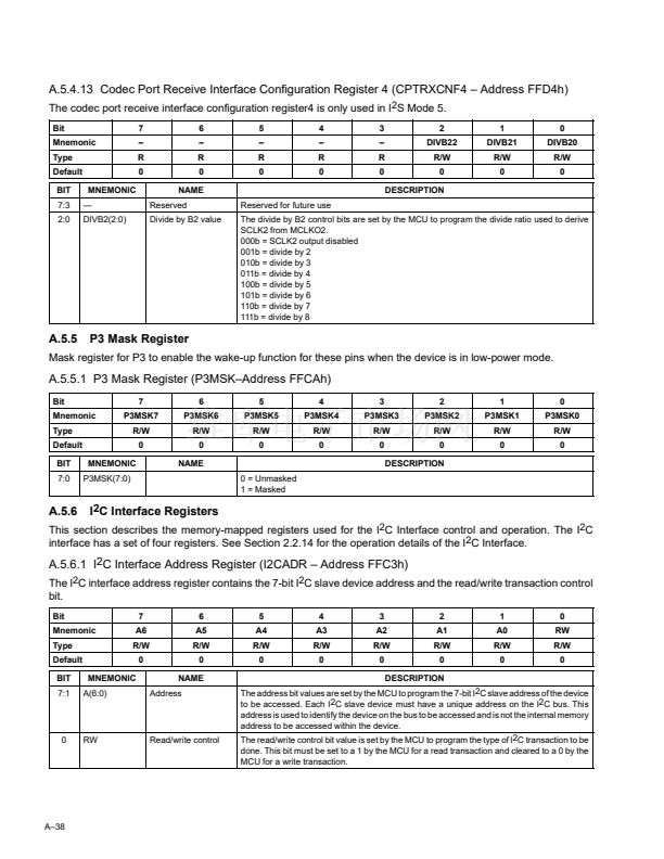
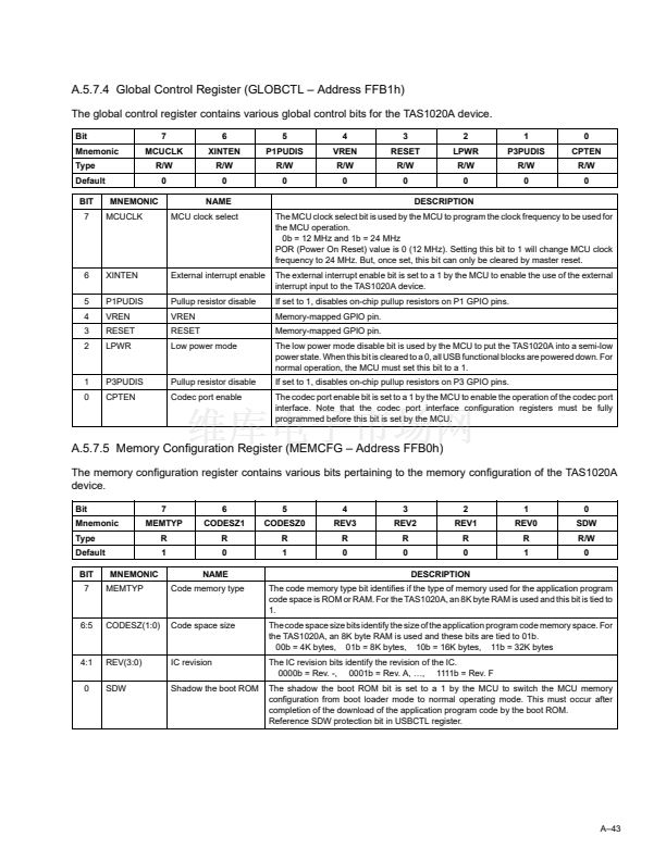
鈥?/div>
I
2
C interface transmit data register empty interrupt: whenever the MCU writes to the I
2
C interface transmit
data register I2CDATO, it results in the hardware clearing the transmit data register empty bit TXE in the
I
2
C interface control and status register I2CCTL. When the data byte is output onto the I
2
C bus, the
hardware sets TXE back to logic 1 and the I
2
C interface transmit data register empty interrupt is issued. The
firmware must clear this interrupt by writing to the interrupt vector register, but this action does not clear the
TXE bit.
I
2
C interface receive data register full interrupt: whenever the I
2
C interface receive data register I2CDATI
receives a byte of data off the I
2
C bus, the hardware sets the receive data register full bit RXF in the I
2
C
interface control and status register I2CCTL and issues the I
2
C interface receive data register full interrupt.
The firmware must clear this interrupt by writing to the interrupt vector register, but this action does not clear
the RXF bit. The RXF bit in the I
2
C interface control and status register I2CCTL is cleared whenever the
MCU reads the contents of the I
2
C interface receive data register I2CDATI.
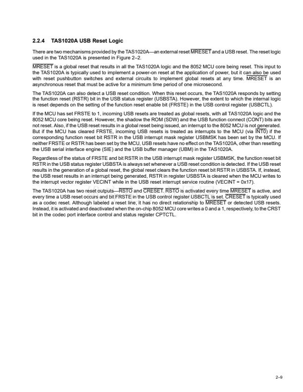
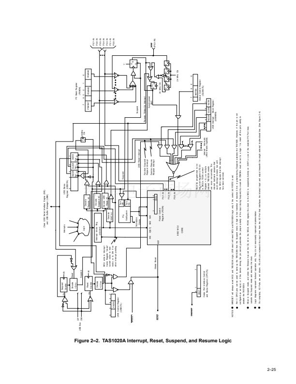
External interrupt XINT: this interrupt is provided to give a user the ability to issue interrupts from external
sources. XINT is logic 0 active. The interrupt is sampled by synchronization logic internal to the TAS1020A,
as shown in Figure 2鈥?. As Figure 2鈥? shows, XINT must be remain in an active-low state for at least one
period of the 24 MHz clock to assure that the interrupt is recognized. Also, XINT must transition to an inactive
state (logic 1) and then transition back to the active state (logic 0) if another XINT interrupt is to be
recognized. If XINT remains in the active low state, it does not result in issuing multiple XINT interrupts. The
firmware must clear this interrupt by writing to the interrupt vector register.
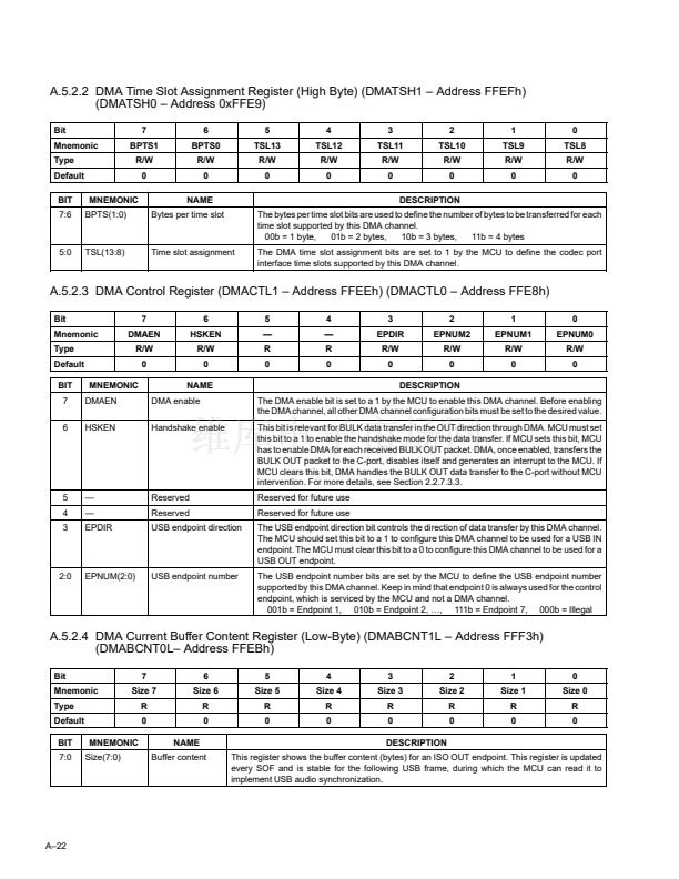
DMA channel 0 interrupt: this interrupt becomes active only during bulk OUT transactions utilizing DMA
channel 0 when the software handshake mode is selected (see Section 2.2.7.3.3). In this mode of operation
the programmable variable DMABPCT 鈥?registers DMABPCT0 and DMABPCT1 鈥?instructs DMA channel
0 as to how many bulk OUT packets it must handle before ceasing operation and issuing the DMA channel
0 interrupt. The firmware must clear this interrupt by writing to the interrupt vector register.
DMA channel 1 interrupt: this interrupt is identical in operation to the DMA channel 0 interrupt. Note that
the same count variable DMABPCT is used for both DMA interrupts. In fact, as described in Section 2.2.12,
only one of the two DMA channels can be active when supporting a bulk OUT transaction. 鈥?thus the need
for only one count variable DMABPCT.
鈥?/div>
鈥?/div>
鈥?/div>
鈥?/div>
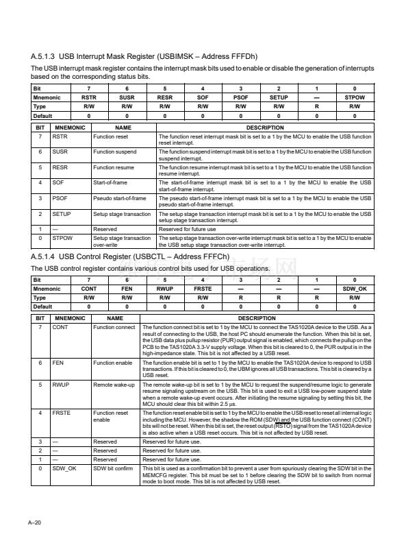
The interrupts for the USB IN endpoints and USB OUT endpoints can be masked. An interrupt for a particular endpoint
occurs at the end of a successful transaction to that endpoint. A status bit for each IN and OUT endpoint also exists.
However, these status bits are read only, and therefore, these bits are intended to be used for diagnostic purposes
only. After a successful transaction to an endpoint, both the interrupt and status bit for an endpoint are asserted until
the interrupt is cleared by the MCU.
The USB function reset, USB function suspend, USB function resume, USB start-of-frame, USB pseudo start-of-
frame, USB setup stage transaction, and USB setup stage transaction over-write interrupts can all be masked. A
status bit for each of these interrupts also exists. Refer to the USB interrupt mask register and the USB status register
for more details. Note that the status bits for these interrupts are read only. For these interrupts, both the interrupt
and status bit are asserted until the interrupt is cleared by the MCU.
The codec port interface transmit data register empty, codec port interface receive data register full, I
2
C interface
transmit data register empty, and I
2
C interface receive data register full interrupts can all be masked. A status bit for
each of these interrupts also exists. Note that the status bits for these interrupts are read only. However, for these
interrupts, the status bits are not cleared automatically when the interrupt is cleared by the MCU. Refer to the codec
port interface control and status register CPTCTL and the I
2
C interface control and status register I2CCTL for more
details.
The external interrupt input (XINT) is logically ORed with the on-chip interrupt sources. An enable bit exists for this
interrupt in the global control register GLOBCTL. This interrupt does not have a status bit.
2鈥?8


 1
1
 2
2
 3
3
 4
4
 5
5
 6
6
 7
7
 8
8
 9
9
 10
10
 11
11
 12
12
 13
13
 14
14
 15
15
 16
16
 17
17
 18
18
 19
19
 20
20
 21
21
 22
22
 23
23
 24
24
 25
25
 26
26
 27
27
 28
28
 29
29
 30
30
 31
31
 32
32
 33
33
 34
34
 35
35
 36
36
 37
37
 38
38
 39
39
 40
40
 41
41
 42
42
 43
43
 44
44
 45
45
 46
46
 47
47
 48
48
 49
49
 50
50
 51
51
 52
52
 53
53
 54
54
 55
55
 56
56
 57
57
 58
58
 59
59
 60
60
 61
61
 62
62
 63
63
 64
64
 65
65
 66
66
 67
67
 68
68
 69
69
 70
70
 71
71
 72
72
 73
73
 74
74
 75
75
 76
76
 77
77
 78
78
 79
79
 80
80
 81
81
 82
82
 83
83
 84
84
 85
85
 86
86
 87
87
 88
88
 89
89
 90
90
 91
91
 92
92
 93
93
 94
94
 95
95
 96
96
 97
97
 98
98
 99
99
 100
100
 101
101
 102
102
 103
103
 104
104
 105
105
 106
106
 107
107
 108
108
 109
109
 110
110
 111
111
 112
112
 113
113
 114
114
