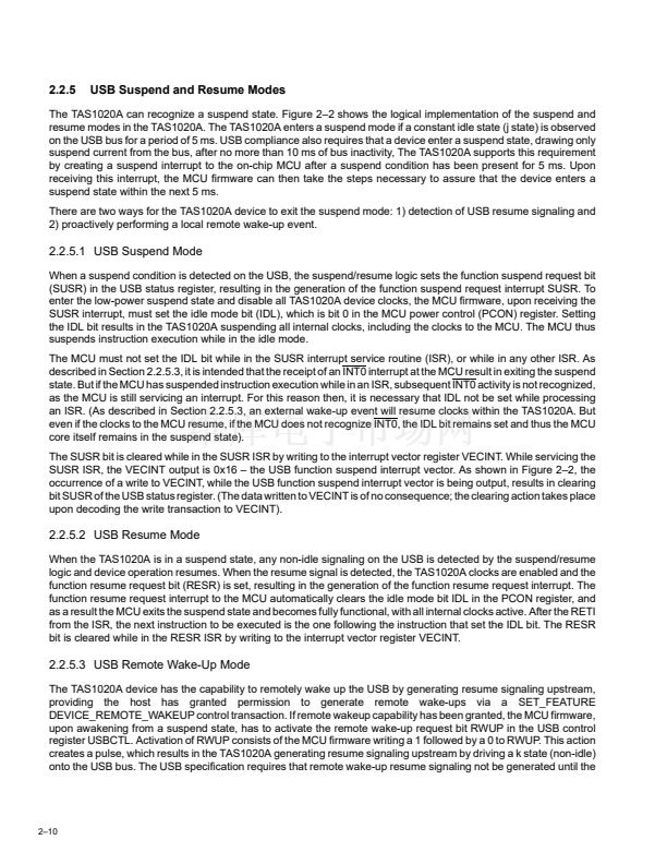
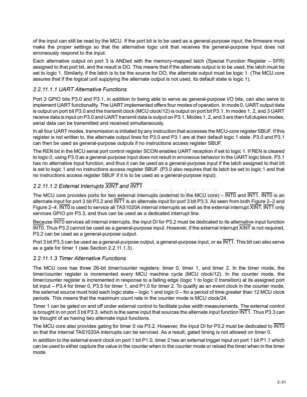
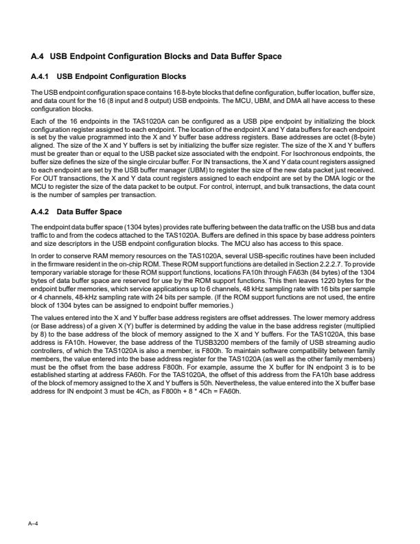
2.2.13.1.4 Byte Reversal Ordering
For all data transactions managed under DMA control, the TAS1020A provides an option to reverse the ordering of
the bytes within a data word as received. Byte order reversal, if selected, applies to both DMA channels. If, for
example, one DMA channel is used to output audio to a codec and the second DMA channel is used to retrieve record
data from a codec, byte reversal is applied to both audio streams.
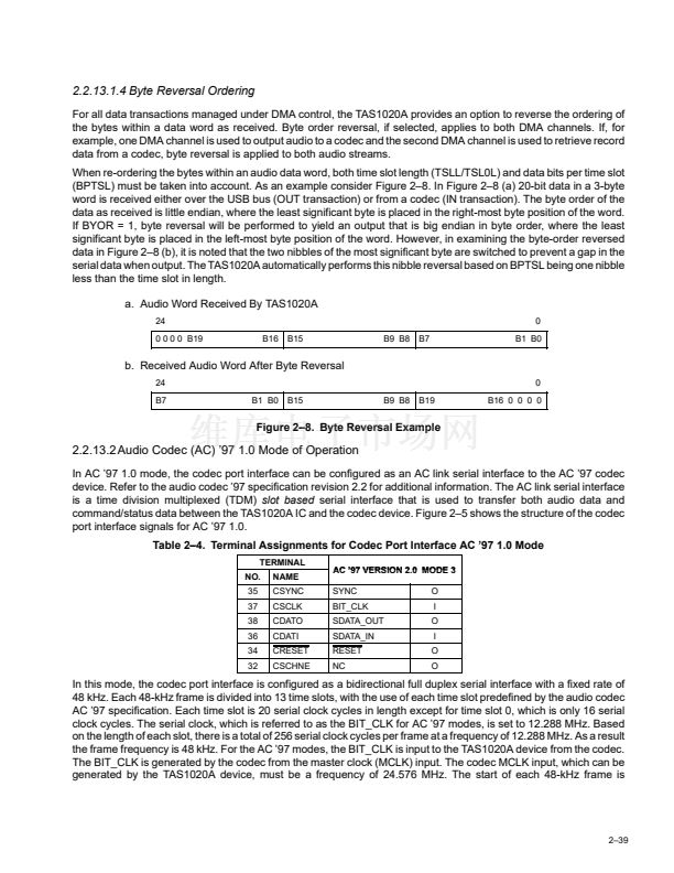
When re-ordering the bytes within an audio data word, both time slot length (TSLL/TSL0L) and data bits per time slot
(BPTSL) must be taken into account. As an example consider Figure 2鈥?. In Figure 2鈥? (a) 20-bit data in a 3-byte
word is received either over the USB bus (OUT transaction) or from a codec (IN transaction). The byte order of the
data as received is little endian, where the least significant byte is placed in the right-most byte position of the word.
If BYOR = 1, byte reversal will be performed to yield an output that is big endian in byte order, where the least
significant byte is placed in the left-most byte position of the word. However, in examining the byte-order reversed
data in Figure 2鈥? (b), it is noted that the two nibbles of the most significant byte are switched to prevent a gap in the
serial data when output. The TAS1020A automatically performs this nibble reversal based on BPTSL being one nibble
less than the time slot in length.
a. Audio Word Received By TAS1020A
24
0 0 0 0 B19
B16
B15
B9 B8
B7
0
B1 B0
b. Received Audio Word After Byte Reversal
24
B7
B1 B0
B15
B9 B8
B19
0
B16 0 0 0 0
Figure 2鈥?. Byte Reversal Example
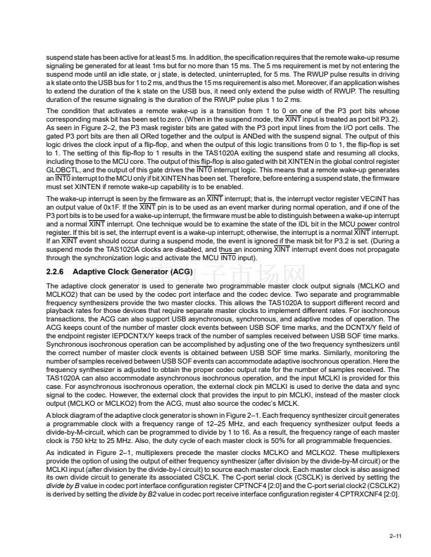
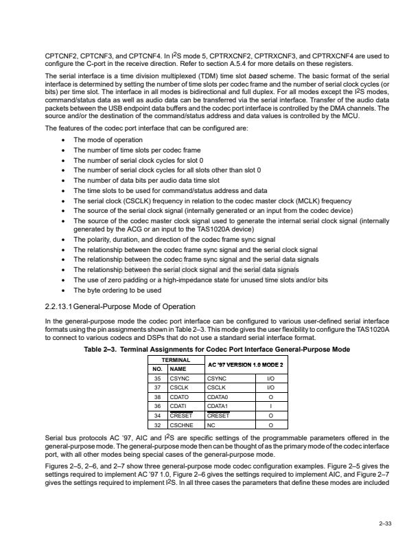
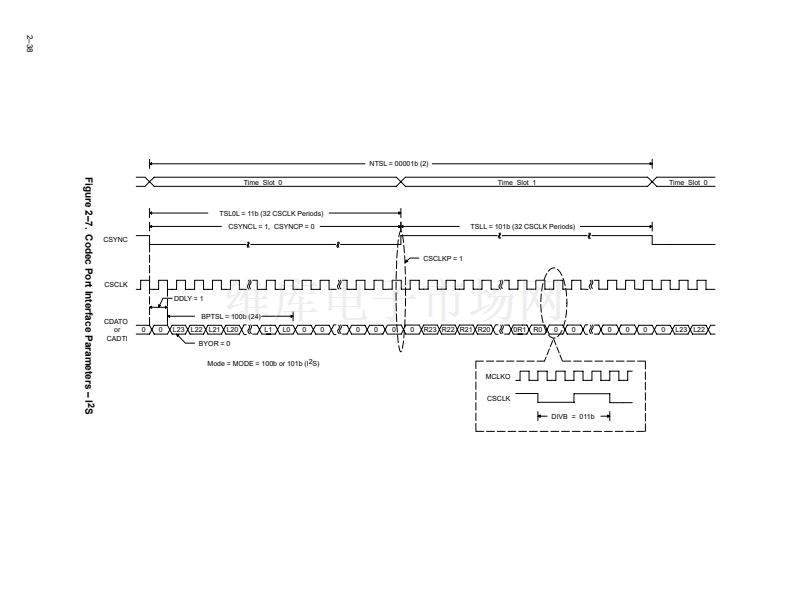
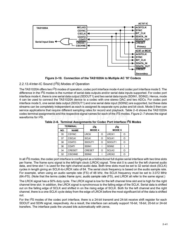
2.2.13.2 Audio Codec (AC) 鈥?7 1.0 Mode of Operation
In AC 鈥?7 1.0 mode, the codec port interface can be configured as an AC link serial interface to the AC 鈥?7 codec
device. Refer to the audio codec 鈥?7 specification revision 2.2 for additional information. The AC link serial interface
is a time division multiplexed (TDM)
slot based
serial interface that is used to transfer both audio data and
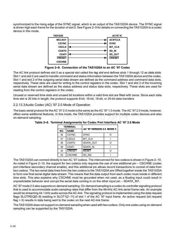
command/status data between the TAS1020A IC and the codec device. Figure 2鈥? shows the structure of the codec
port interface signals for AC 鈥?7 1.0.
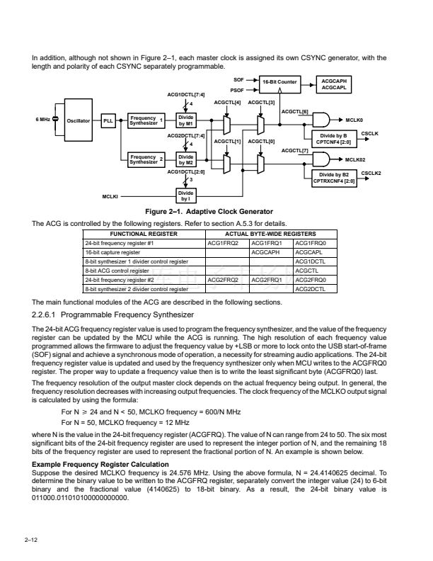
Table 2鈥?. Terminal Assignments for Codec Port Interface AC 鈥?7 1.0 Mode
TERMINAL
NO.
35
37
38
36
34
32
NAME
CSYNC
CSCLK
CDATO
CDATI
CRESET
CSCHNE
AC 鈥?7 VERSION 2.0 MODE 3
20
SYNC
BIT_CLK
SDATA_OUT
SDATA_IN
RESET
NC
O
I
O
I
O
O
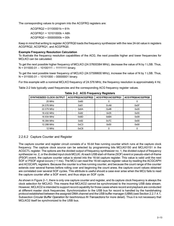
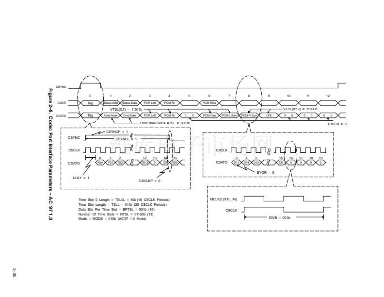
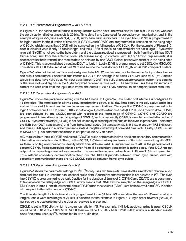
In this mode, the codec port interface is configured as a bidirectional full duplex serial interface with a fixed rate of
48 kHz. Each 48-kHz frame is divided into 13 time slots, with the use of each time slot predefined by the audio codec
AC 鈥?7 specification. Each time slot is 20 serial clock cycles in length except for time slot 0, which is only 16 serial
clock cycles. The serial clock, which is referred to as the BIT_CLK for AC 鈥?7 modes, is set to 12.288 MHz. Based
on the length of each slot, there is a total of 256 serial clock cycles per frame at a frequency of 12.288 MHz. As a result
the frame frequency is 48 kHz. For the AC 鈥?7 modes, the BIT_CLK is input to the TAS1020A device from the codec.
The BIT_CLK is generated by the codec from the master clock (MCLK) input. The codec MCLK input, which can be
generated by the TAS1020A device, must be a frequency of 24.576 MHz. The start of each 48-kHz frame is
2鈥?9


 1
1
 2
2
 3
3
 4
4
 5
5
 6
6
 7
7
 8
8
 9
9
 10
10
 11
11
 12
12
 13
13
 14
14
 15
15
 16
16
 17
17
 18
18
 19
19
 20
20
 21
21
 22
22
 23
23
 24
24
 25
25
 26
26
 27
27
 28
28
 29
29
 30
30
 31
31
 32
32
 33
33
 34
34
 35
35
 36
36
 37
37
 38
38
 39
39
 40
40
 41
41
 42
42
 43
43
 44
44
 45
45
 46
46
 47
47
 48
48
 49
49
 50
50
 51
51
 52
52
 53
53
 54
54
 55
55
 56
56
 57
57
 58
58
 59
59
 60
60
 61
61
 62
62
 63
63
 64
64
 65
65
 66
66
 67
67
 68
68
 69
69
 70
70
 71
71
 72
72
 73
73
 74
74
 75
75
 76
76
 77
77
 78
78
 79
79
 80
80
 81
81
 82
82
 83
83
 84
84
 85
85
 86
86
 87
87
 88
88
 89
89
 90
90
 91
91
 92
92
 93
93
 94
94
 95
95
 96
96
 97
97
 98
98
 99
99
 100
100
 101
101
 102
102
 103
103
 104
104
 105
105
 106
106
 107
107
 108
108
 109
109
 110
110
 111
111
 112
112
 113
113
 114
114
