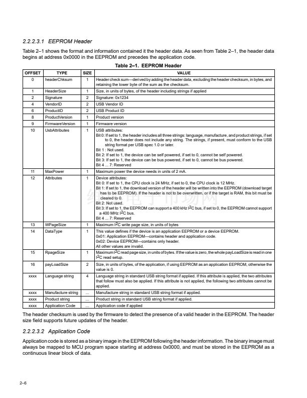
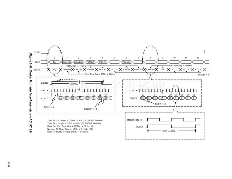
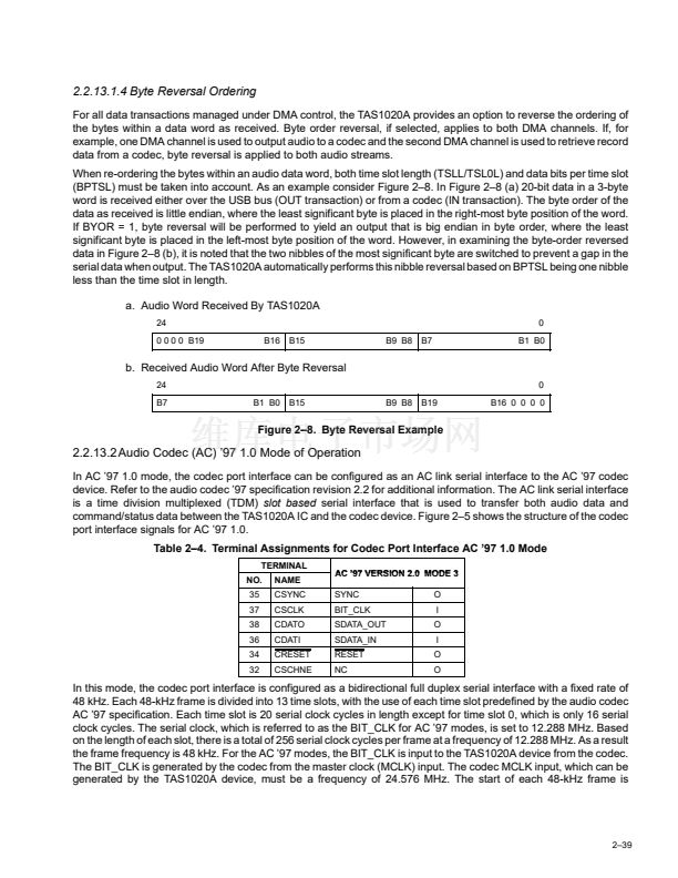
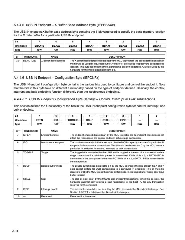
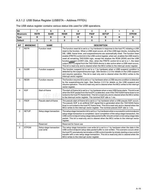
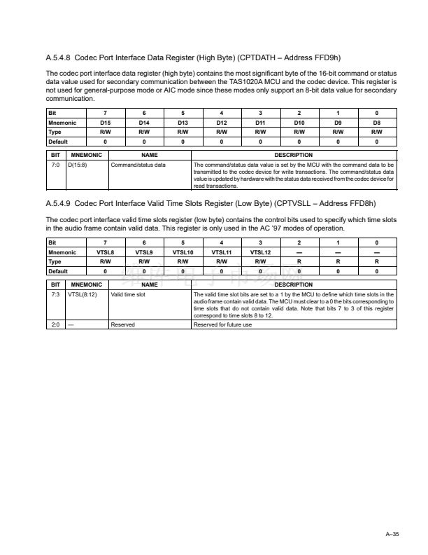
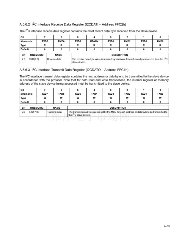
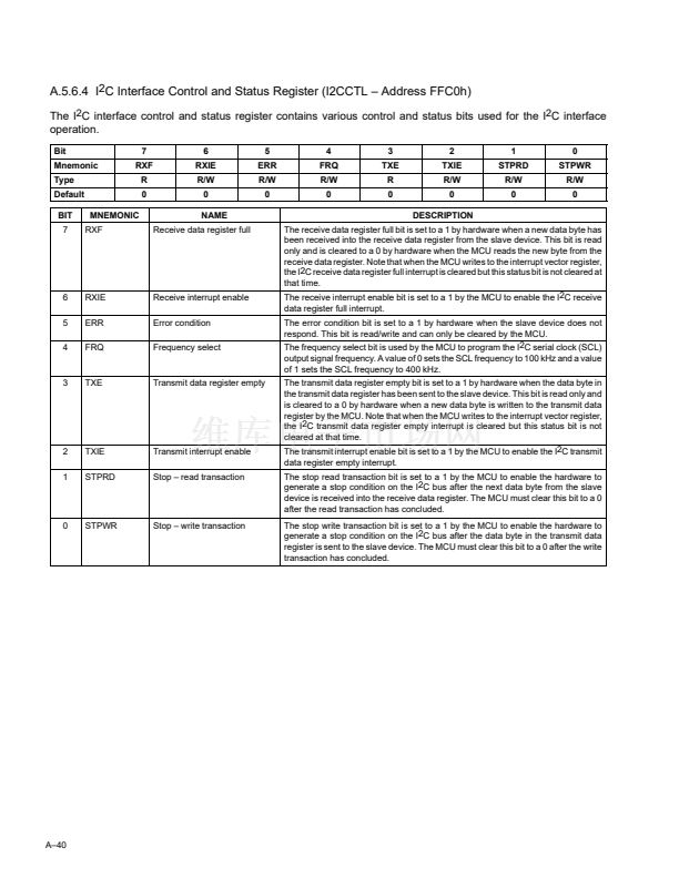
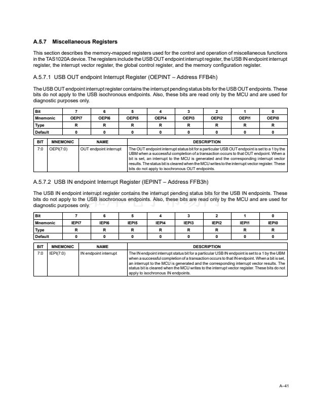
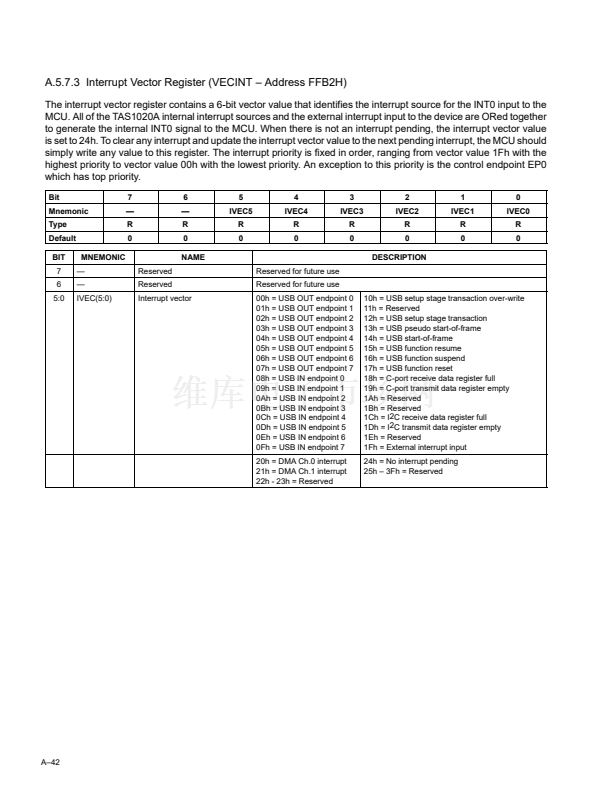
AC鈥?7 IC
TAS1020A
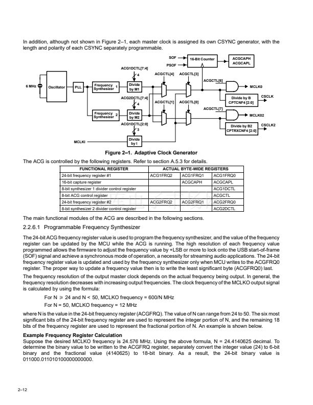
MCLKO
CSYNC
CSCLK
CDATO
CDATI
CRESET
CSCHNE
AC97CLK
SYNC
BIT_CLK
SDATA_IN
SDATA_OUT
CRESET
Primary
AC97 or MC97
AC97CLK
SYNC
BIT_CLK
SDATA_IN
SDATA_OUT
CRESET
Secondary
Serial Input Data
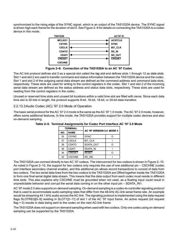
Figure 2鈥?0. Connection of the TAS1020A to Multiple AC 鈥?7 Codecs
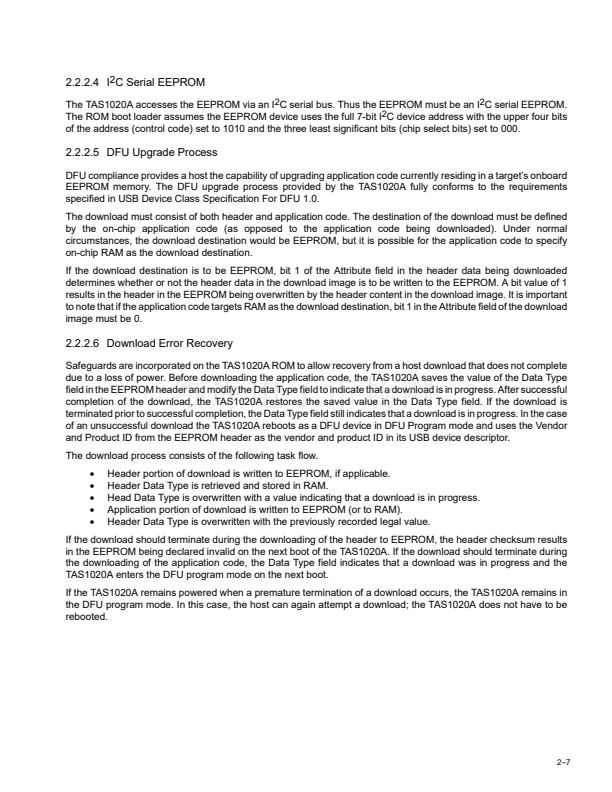
2.2.13.4 Inter-IC Sound (I
2
S) Modes of Operation
The TAS1020A offers two I
2
S modes of operation, codec port interface mode 4 and codec port interface mode 5. The
difference in the I
2
S modes is the number of serial data outputs and/or serial data inputs supported. For codec port
interface mode 4, there is one serial data output (SDOUT1) and two serial data inputs (SDIN1, SDIN2). Hence, mode
4 can be used to connect the TAS1020A device to a codec with one stereo DAC and two ADCs. For codec port
interface mode 5, one serial data output (SDOUT1) and one serial data input (SDIN2) are supported, but these data
streams can be completely independent as each is assigned its separate sync pulse and bit clock. Mode 5 then can
service applications that require different sampling rates for record and playback. Table 2鈥? shows the TAS1020A
codec terminal assignments and the respective signal names for each of the I
2
S modes. Figure 2鈥? shows the signal
waveforms for I
2
S.
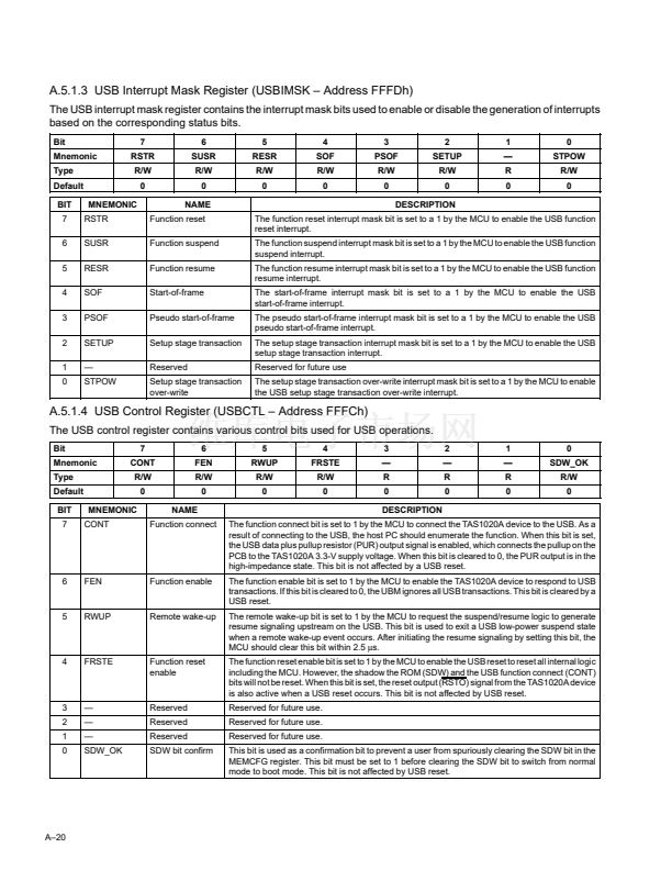
Table 2鈥?. Terminal Assignments for Codec Port Interface I
2
S Modes
TERMINAL
NO.
35
37
38
36
34
32
NAME
CSYNC
CSCLK
CDATO
CDATI
CRESET
CSCHNE
I2S
MODE 4
LRCK
SCLK
SDOUT1
SDIN1
CRESET
SDIN2
O
O
O
I
O
I
I2S
MODE 5
LRCK1
SCLK1
SDOUT1
SDIN2
SCLK2
LRCK2
O
O
O
I
O
O
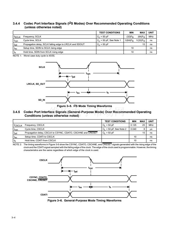
In all I
2
S modes, the codec port interface is configured as a bidirectional full duplex serial interface with two time slots
per frame. The frame sync signal is the left/right clock (LRCK) signal. Time slot 0 is used for the left channel audio
data, and time slot 1 is used for the right channel audio data. Both time slots must be set to 32 serial clock (SCLK)
cycles in length giving an SCLK-to-LRCK ratio of 64. The serial clock frequency is based on the audio sample rate.
For example, when using an audio sample rate (FS) of 48 kHz, the SCLK frequency must be set to 3.072 MHz
(64脳FS). (Note that the terms
codec frame sync, audio sample rate
(FS), and
LRCK
all refer to the same signal.)
The LRCK signal has a 50% duty cycle. The LRCK signal is low for the left channel time slot and is high for the right
channel time slot. In addition, the LRCK signal is synchronous to the falling edge of the SCLK. Serial data is shifted
out on the falling edge of SCLK and shifted in on the rising edge of SCLK. Both for the left channel and the right
channel, there is a one-SCLK cycle delay from the edge of LRCK before the most significant bit of the data is shifted
out.
For the I
2
S modes of the codec port interface, there is a 24-bit transmit and 24-bit receive shift register for each
SDOUT and SDIN signal, respectively. As a result, the interface can actually support 16-bit, 18-bit, 20-bit or 24-bit
transfers. The interface pads the unused bits automatically with zeros.
2鈥?1


 1
1
 2
2
 3
3
 4
4
 5
5
 6
6
 7
7
 8
8
 9
9
 10
10
 11
11
 12
12
 13
13
 14
14
 15
15
 16
16
 17
17
 18
18
 19
19
 20
20
 21
21
 22
22
 23
23
 24
24
 25
25
 26
26
 27
27
 28
28
 29
29
 30
30
 31
31
 32
32
 33
33
 34
34
 35
35
 36
36
 37
37
 38
38
 39
39
 40
40
 41
41
 42
42
 43
43
 44
44
 45
45
 46
46
 47
47
 48
48
 49
49
 50
50
 51
51
 52
52
 53
53
 54
54
 55
55
 56
56
 57
57
 58
58
 59
59
 60
60
 61
61
 62
62
 63
63
 64
64
 65
65
 66
66
 67
67
 68
68
 69
69
 70
70
 71
71
 72
72
 73
73
 74
74
 75
75
 76
76
 77
77
 78
78
 79
79
 80
80
 81
81
 82
82
 83
83
 84
84
 85
85
 86
86
 87
87
 88
88
 89
89
 90
90
 91
91
 92
92
 93
93
 94
94
 95
95
 96
96
 97
97
 98
98
 99
99
 100
100
 101
101
 102
102
 103
103
 104
104
 105
105
 106
106
 107
107
 108
108
 109
109
 110
110
 111
111
 112
112
 113
113
 114
114
