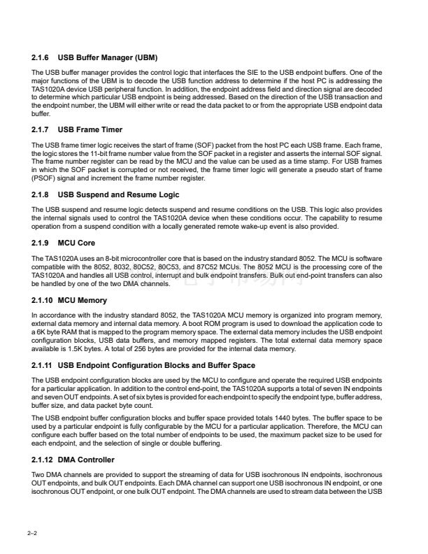
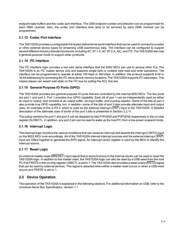
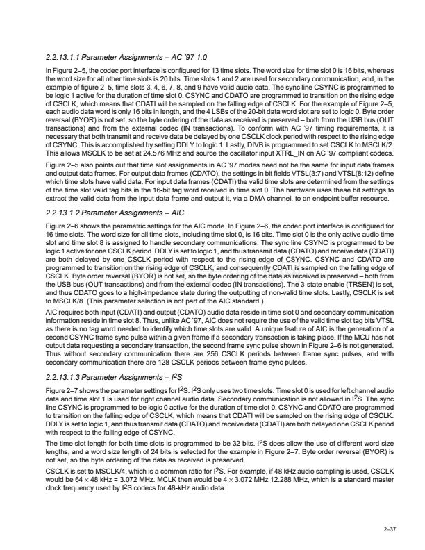
Figure 2鈥? shows the parameter settings for the AIC master or slave mode, and Section 2.2.13.1.2 provides detail
on these settings. Table 2鈥? shows the TAS1020A codec terminal assignments and the respective signal names for
the AIC mode of operation.
Table 2鈥?. Terminal Assignments for Codec Port Interface AIC Mode
TERMINAL
NO.
35
37
38
36
34
32
NAME
CSYNC
CSCLK
CDATO
CDATI
CRESET
CSCHNE
FS
SCLK
DOUT
DIN
RESET
FC
AIC
O
O
O
I
O
O
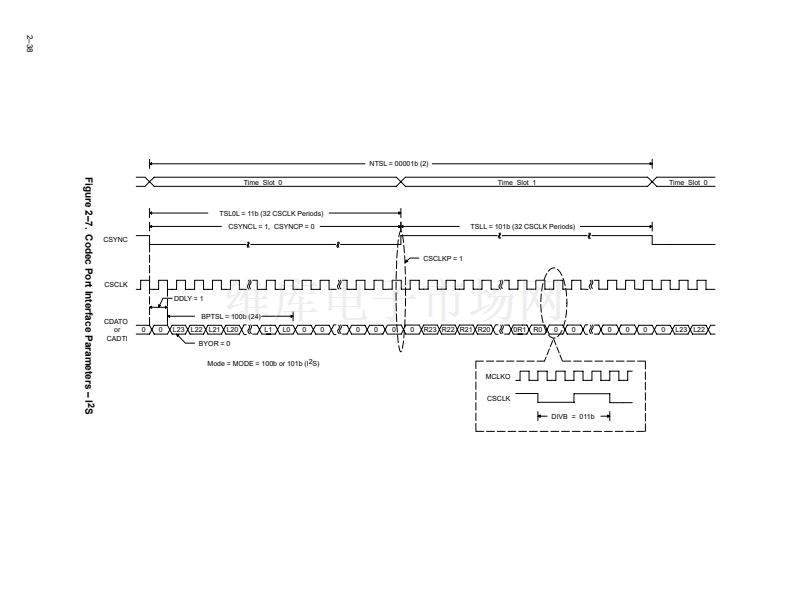
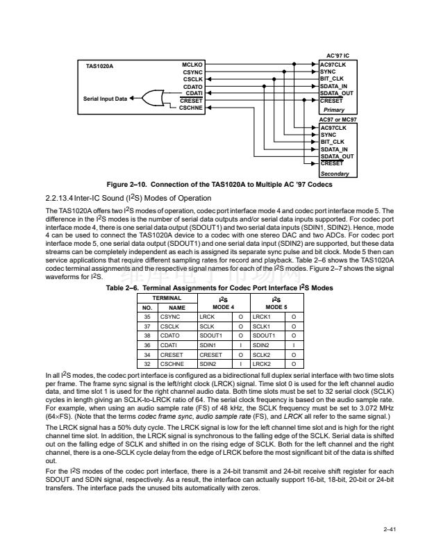
2.2.13.6 Bulk Mode
The TAS1020A supports bulk OUT data transactions through the codec port using one of the two available DMA
channels, but the codec port needs to be configured in AC97 or general-purpose mode to support bulk OUT
transactions. AC 鈥?7 and the general-purpose mode are the only two modes of operation that support bulk OUT
transactions, as these are the only two modes that have mechanisms in place to distinguish when valid data is or is
not being output. AC 鈥?7 uses tag bits to indicate whether or not data is valid in any given time slot. In the
general-purpose mode, no sync pulse is output if no valid data is available to be output. (In both AC 鈥?7 and the
general-purpose mode, CPTBLK must be set to logic 1 if tag bits or the sync pulse, respectively, are to indicate the
presence of valid data). See Section 2.2.7.3.3 for more detail on bulk OUT transactions using one of the two DMA
channels.
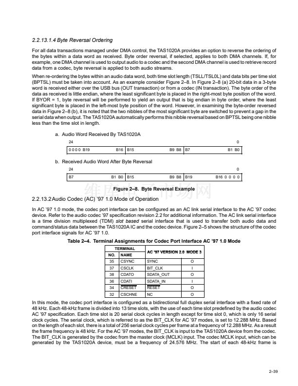
2.2.14 I
2
C Interface
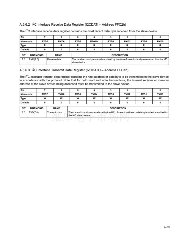
The TAS1020A has a bidirectional two-wire serial interface that can be used to access other ICs. This serial interface
is compatible with the I
2
C (Inter IC) bus protocol and supports both 100-kbps and 400-kbps data transfer rates. The
TAS1020A does not support all provisions of the I
2
C specification. The TAS1020A can only serve as a master device
on the I
2
C bus, but as a master device, the TAS1020A does not support a multimaster bus environment (no bus
arbitration), but can recognize wait state insertions on the bus. The I
2
C interface on the TAS1020A is provided to allow
access to I
2
C slave devices, including EEPROMs and codecs. For example, if the application program code is stored
in an EEPROM on the PCB, then the MCU downloads the code from the EEPROM to the TAS1020A on-chip RAM
using the I
2
C interface. Another example is the control of a codec device that uses an I
2
S interface for audio data
transfers and an I
2
C interface for control register read/write access.
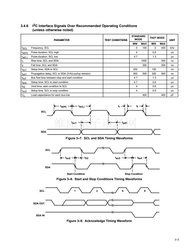
2.2.14.1 Data Transfers
The two-wire serial interface uses the serial clock signal, SCL, and the serial data signal, SDA. As stated above, the
TAS1020A is a master only device, and therefore, the SCL signal is an output only. The SDA signal is a bidirectional
signal that uses an open-drain output to allow the TAS1020A to be wire-ORed with other devices that use open-drain
or open-collector outputs.
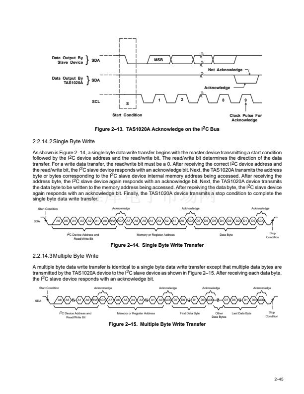
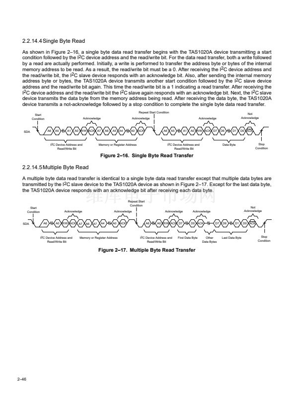
All read and write data transfers on the serial bus are initiated by the TAS1020A. The TAS1020A is also responsible
for generating the clock signal used for all data transfers. The data is transferred on the bus serially one bit at a time.
However, the protocol requires that the address and data be transferred in byte (8-bit) format with the most-significant
bit (MSB) transferred first. In addition, each byte transferred on the bus is acknowledged by the receiving device with
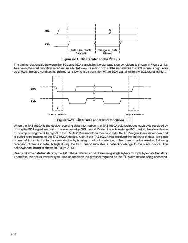
an acknowledge bit. Each transfer operation begins with the master device driving a start condition on the bus and
ends with the master device driving a stop condition on the bus.
The timing relationship between the SCL and SDA signals for each bit transferred on the bus is shown in Figure 2鈥?1.
As shown, the SDA signal must be stable while the SCL signal is high, which also means that the SDA signal can
only change states while the SCL signal is low.
2鈥?3


 1
1
 2
2
 3
3
 4
4
 5
5
 6
6
 7
7
 8
8
 9
9
 10
10
 11
11
 12
12
 13
13
 14
14
 15
15
 16
16
 17
17
 18
18
 19
19
 20
20
 21
21
 22
22
 23
23
 24
24
 25
25
 26
26
 27
27
 28
28
 29
29
 30
30
 31
31
 32
32
 33
33
 34
34
 35
35
 36
36
 37
37
 38
38
 39
39
 40
40
 41
41
 42
42
 43
43
 44
44
 45
45
 46
46
 47
47
 48
48
 49
49
 50
50
 51
51
 52
52
 53
53
 54
54
 55
55
 56
56
 57
57
 58
58
 59
59
 60
60
 61
61
 62
62
 63
63
 64
64
 65
65
 66
66
 67
67
 68
68
 69
69
 70
70
 71
71
 72
72
 73
73
 74
74
 75
75
 76
76
 77
77
 78
78
 79
79
 80
80
 81
81
 82
82
 83
83
 84
84
 85
85
 86
86
 87
87
 88
88
 89
89
 90
90
 91
91
 92
92
 93
93
 94
94
 95
95
 96
96
 97
97
 98
98
 99
99
 100
100
 101
101
 102
102
 103
103
 104
104
 105
105
 106
106
 107
107
 108
108
 109
109
 110
110
 111
111
 112
112
 113
113
 114
114
