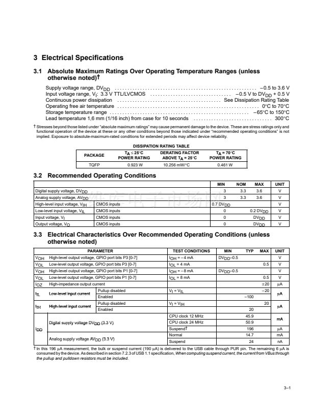
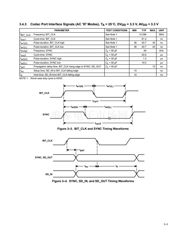
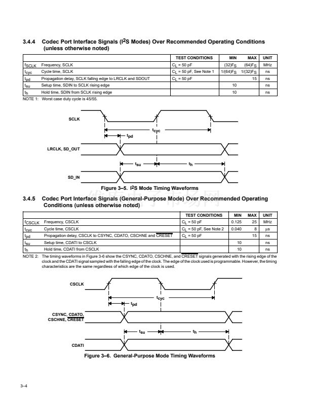
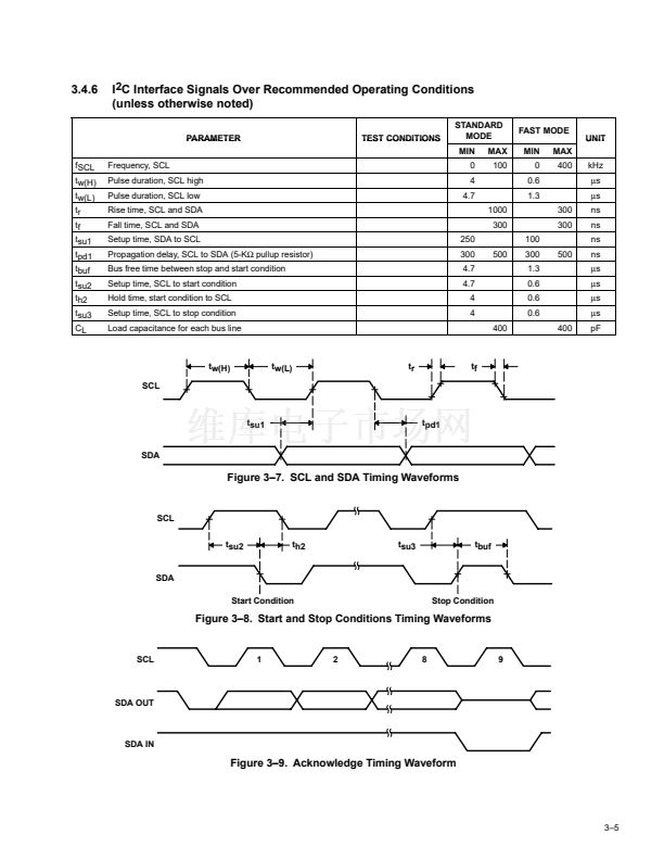
3.4 Timing Characteristics
3.4.1
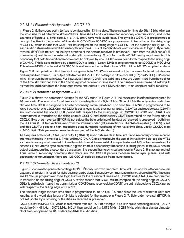
Clock and Control Signals Over Recommended Operating Conditions
(unless otherwise noted)
PARAMETER
Internal
fMCLKO1
fMCLKO2
fMCLKI
tw(L)
Clock frequency, MCLKO1
frequency
Clock frequency, MCLKO2
frequency
Clock frequency, MCLKI
Pulse duration, XINT low
MCLKI
Internal
MCLKI
CL = 50 pF, See Note 1
pF
See Note 1
CL = 50 pF
CL = 50 pF, See Note 1
pF
TEST CONDITIONS
MIN
0.75
0.625
0.75
0.625
5
0.2
MAX
25
25
25
25
25
10
MHz
MHz
碌s
MHz
UNIT
NOTE 1: Worst case duty cycle is 45/55.
tw(L)
XINT
Figure 3鈥?. External Interrupt Timing Waveform
3.4.2
USB Signals When Sourced by TAS1020A Over Recommended Operating Conditions
(unless otherwise noted)
PARAMETER
TEST CONDITIONS
MIN
4
4
(tr / tf)
脳
100
90%
1.3
VOH
VOL
MAX
20
20
110%
2
V
UNIT
ns
ns
Transition rise time for DP or DM
Transition fall time for DP or DM
Rise/fall time matching
Voltage output signal crossover
DM
VO(CRS)
DP
tr
tf
tRFM
VO(CRS)
90%
10%
tr , t f
Figure 3鈥?. USB Differential Driver Timing Waveform
3鈥?


 1
1
 2
2
 3
3
 4
4
 5
5
 6
6
 7
7
 8
8
 9
9
 10
10
 11
11
 12
12
 13
13
 14
14
 15
15
 16
16
 17
17
 18
18
 19
19
 20
20
 21
21
 22
22
 23
23
 24
24
 25
25
 26
26
 27
27
 28
28
 29
29
 30
30
 31
31
 32
32
 33
33
 34
34
 35
35
 36
36
 37
37
 38
38
 39
39
 40
40
 41
41
 42
42
 43
43
 44
44
 45
45
 46
46
 47
47
 48
48
 49
49
 50
50
 51
51
 52
52
 53
53
 54
54
 55
55
 56
56
 57
57
 58
58
 59
59
 60
60
 61
61
 62
62
 63
63
 64
64
 65
65
 66
66
 67
67
 68
68
 69
69
 70
70
 71
71
 72
72
 73
73
 74
74
 75
75
 76
76
 77
77
 78
78
 79
79
 80
80
 81
81
 82
82
 83
83
 84
84
 85
85
 86
86
 87
87
 88
88
 89
89
 90
90
 91
91
 92
92
 93
93
 94
94
 95
95
 96
96
 97
97
 98
98
 99
99
 100
100
 101
101
 102
102
 103
103
 104
104
 105
105
 106
106
 107
107
 108
108
 109
109
 110
110
 111
111
 112
112
 113
113
 114
114
