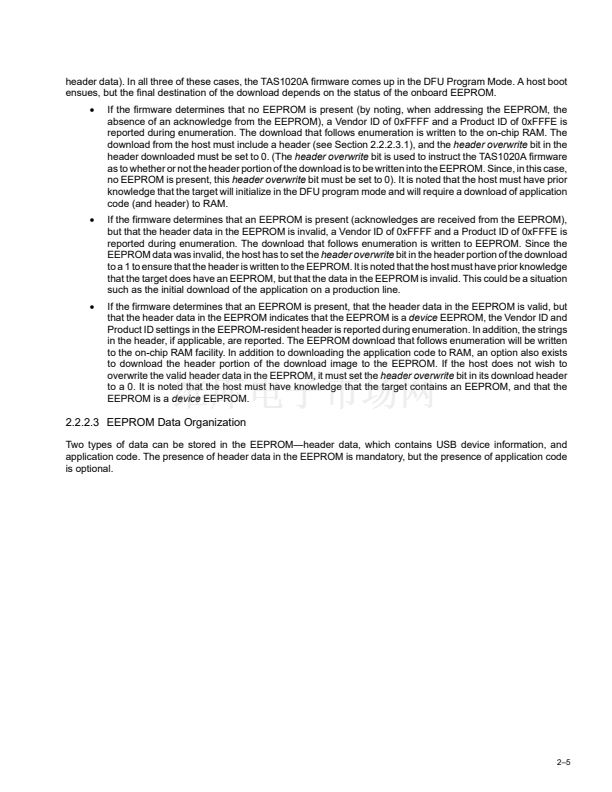
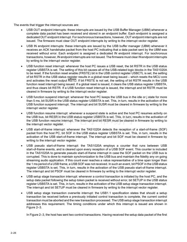
3.4.4
Codec Port Interface Signals (I
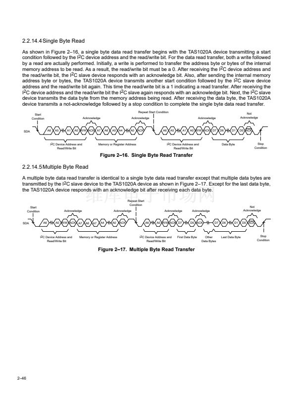
2
S Modes) Over Recommended Operating Conditions
(unless otherwise noted)
TEST CONDITIONS
MIN
(32)FS
1/(64)FS
10
10
MAX
(64)FS
1/(32)FS
15
UNIT
MHz
ns
ns
ns
ns
Frequency, SCLK
Cycle time, SCLK
Propagation delay, SCLK falling edge to LRCLK and SDOUT
Setup time, SDIN to SCLK rising edge
CL = 50 pF
CL = 50 pF, See Note 1
CL = 50 pF
fSCLK
tcyc
tpd
tsu
th
Hold time, SDIN from SCLK rising edge
NOTE 1: Worst case duty cycle is 45/55.
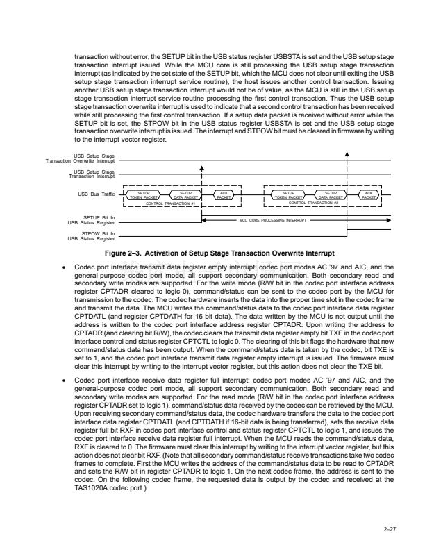
SCLK
tcyc
tpd
LRCLK, SD_OUT
tsu
SD_IN
th
Figure 3鈥?. I
2
S Mode Timing Waveforms
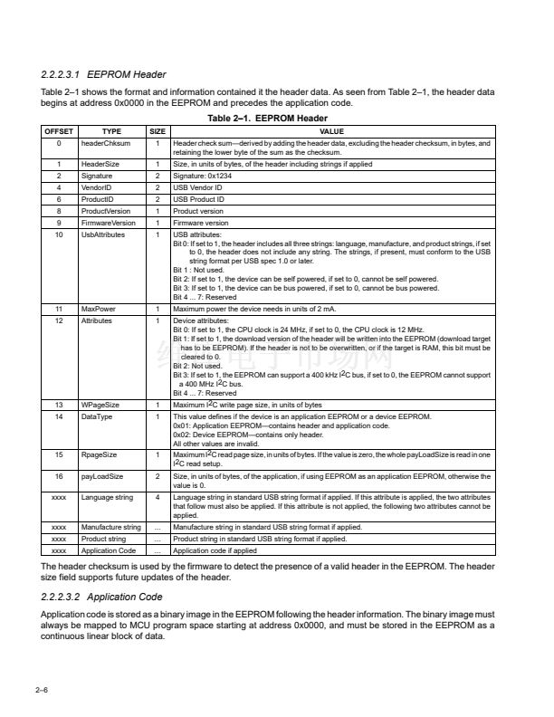
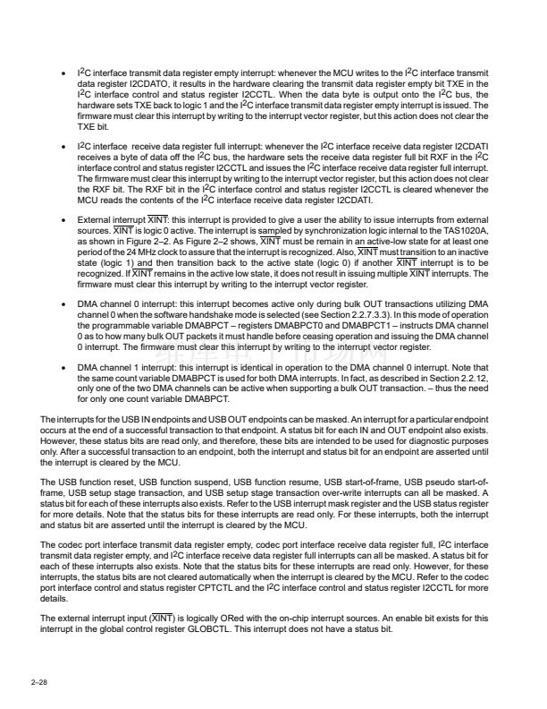
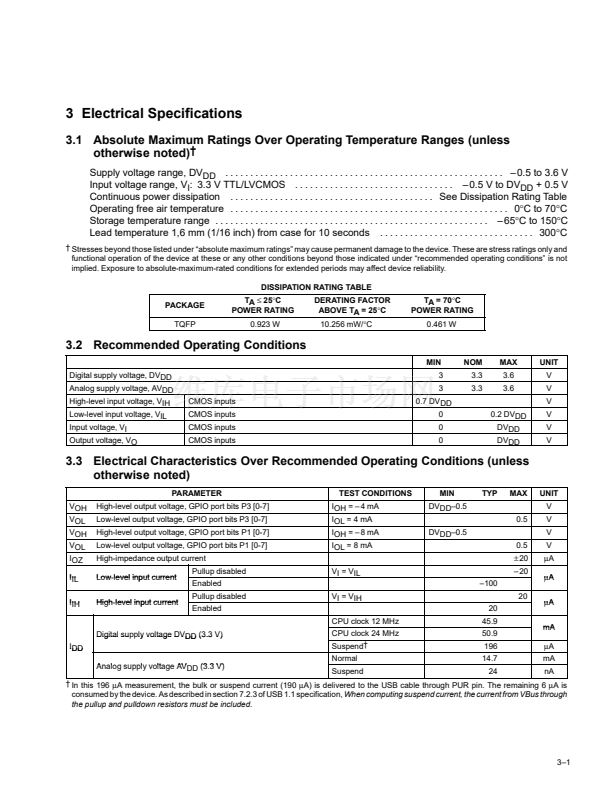
3.4.5
Codec Port Interface Signals (General-Purpose Mode) Over Recommended Operating
Conditions (unless otherwise noted)
TEST CONDITIONS
MIN
0.125
0.040
10
MAX
25
8
15
UNIT
MHz
碌s
ns
ns
Frequency, CSCLK
Cycle time, CSCLK
Propagation delay, CSCLK to CSYNC, CDATO, CSCHNE and CRESET
Setup time, CDATI to CSCLK
CL = 50 pF
CL = 50 pF, See Note 2
CL = 50 pF
fCSCLK
tcyc
tpd
tsu
th
Hold time, CDATI from CSCLK
10
ns
NOTE 2: The timing waveforms in Figure 3-6 show the CSYNC, CDATO, CSCHNE, and CRESET signals generated with the rising edge of the
clock and the CDATI signal sampled with the falling edge of the clock. The edge of the clock used is programmable. However, the timing
characteristics are the same regardless of which edge of the clock is used.
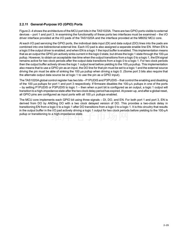
CSCLK
tcyc
tpd
CSYNC, CDATO,
CSCHNE, CRESET
tsu
CDATI
th
Figure 3鈥?. General-Purpose Mode Timing Waveforms
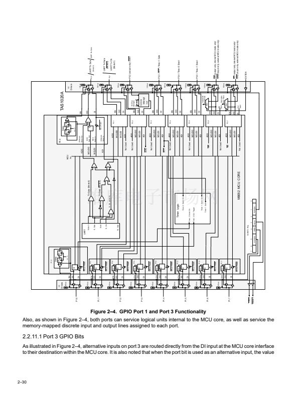
3鈥?


 1
1
 2
2
 3
3
 4
4
 5
5
 6
6
 7
7
 8
8
 9
9
 10
10
 11
11
 12
12
 13
13
 14
14
 15
15
 16
16
 17
17
 18
18
 19
19
 20
20
 21
21
 22
22
 23
23
 24
24
 25
25
 26
26
 27
27
 28
28
 29
29
 30
30
 31
31
 32
32
 33
33
 34
34
 35
35
 36
36
 37
37
 38
38
 39
39
 40
40
 41
41
 42
42
 43
43
 44
44
 45
45
 46
46
 47
47
 48
48
 49
49
 50
50
 51
51
 52
52
 53
53
 54
54
 55
55
 56
56
 57
57
 58
58
 59
59
 60
60
 61
61
 62
62
 63
63
 64
64
 65
65
 66
66
 67
67
 68
68
 69
69
 70
70
 71
71
 72
72
 73
73
 74
74
 75
75
 76
76
 77
77
 78
78
 79
79
 80
80
 81
81
 82
82
 83
83
 84
84
 85
85
 86
86
 87
87
 88
88
 89
89
 90
90
 91
91
 92
92
 93
93
 94
94
 95
95
 96
96
 97
97
 98
98
 99
99
 100
100
 101
101
 102
102
 103
103
 104
104
 105
105
 106
106
 107
107
 108
108
 109
109
 110
110
 111
111
 112
112
 113
113
 114
114
