A.4 USB Endpoint Configuration Blocks and Data Buffer Space
A.4.1
USB Endpoint Configuration Blocks
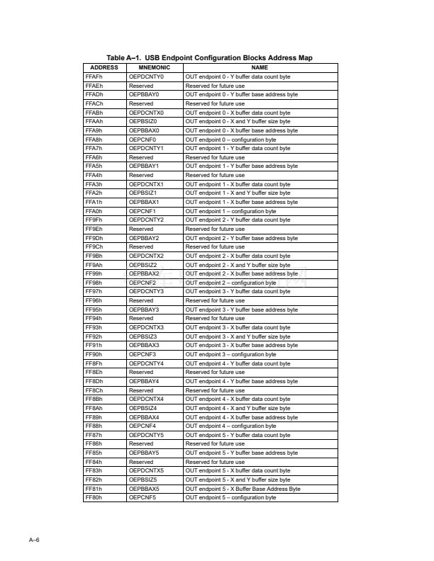
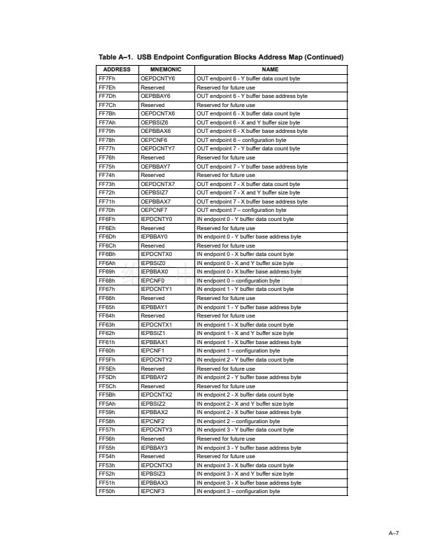
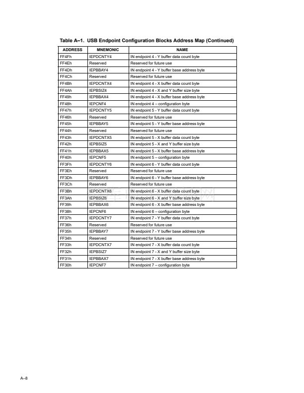
The USB endpoint configuration space contains 16 8-byte blocks that define configuration, buffer location, buffer size,
and data count for the 16 (8 input and 8 output) USB endpoints. The MCU, UBM, and DMA all have access to these
configuration blocks.
Each of the 16 endpoints in the TAS1020A can be configured as a USB pipe endpoint by initializing the block
configuration register assigned to each endpoint. The location of the endpoint X and Y data buffers for each endpoint
is set by the value programmed into the X and Y buffer base address registers. Base addresses are octet (8-byte)
aligned. The size of the X and Y buffers is set by initializing the buffer size register. The size of the X and Y buffers
must be greater than or equal to the USB packet size associated with the endpoint. For Isochronous endpoints, the
buffer size defines the size of the single circular buffer. For IN transactions, the X and Y data count registers assigned
to each endpoint are set by the USB buffer manager (UBM) to register the size of the new data packet just received.
For OUT transactions, the X and Y data count registers assigned to each endpoint are set by the DMA logic or the
MCU to register the size of the data packet to be output. For control, interrupt, and bulk transactions, the data count
is the number of samples per transaction.
A.4.2
Data Buffer Space
The endpoint data buffer space (1304 bytes) provides rate buffering between the data traffic on the USB bus and data
traffic to and from the codecs attached to the TAS1020A. Buffers are defined in this space by base address pointers
and size descriptors in the USB endpoint configuration blocks. The MCU also has access to this space.
In order to conserve RAM memory resources on the TAS1020A, several USB-specific routines have been included
in the firmware resident in the on-chip ROM. These ROM support functions are detailed in Section 2.2.2.7. To provide
temporary variable storage for these ROM support functions, locations FA10h through FA63h (84 bytes) of the 1304
bytes of data buffer space are reserved for use by the ROM support functions. This then leaves 1220 bytes for the
endpoint buffer memories, which service applications up to 6 channels, 48 kHz sampling rate with 16 bits per sample
or 4 channels, 48-kHz sampling rate with 24 bits per sample. (If the ROM support functions are not used, the entire
block of 1304 bytes can be assigned to endpoint buffer memories.)
The values entered into the X and Y buffer base address registers are offset addresses. The lower memory address
(or Base address) of a given X (Y) buffer is determined by adding the value in the base address register (multiplied
by 8) to the base address of the block of memory assigned to the X and Y buffers. For the TAS1020A, this base
address is FA10h. However, the base address of the TUSB3200 members of the family of USB streaming audio
controllers, of which the TAS1020A is also a member, is F800h. To maintain software compatibility between family
members, the value entered into the base address register for the TAS1020A (as well as the other family members)
must be the offset from the base address F800h. For example, assume the X buffer for IN endpoint 3 is to be
established starting at address FA60h. For the TAS1020A, the offset of this address from the FA10h base address
of the block of memory assigned to the X and Y buffers is 50h. Nevertheless, the value entered into the X buffer base
address for IN endpoint 3 must be 4Ch, as F800h + 8 * 4Ch = FA60h.
A鈥?


 1
1
 2
2
 3
3
 4
4
 5
5
 6
6
 7
7
 8
8
 9
9
 10
10
 11
11
 12
12
 13
13
 14
14
 15
15
 16
16
 17
17
 18
18
 19
19
 20
20
 21
21
 22
22
 23
23
 24
24
 25
25
 26
26
 27
27
 28
28
 29
29
 30
30
 31
31
 32
32
 33
33
 34
34
 35
35
 36
36
 37
37
 38
38
 39
39
 40
40
 41
41
 42
42
 43
43
 44
44
 45
45
 46
46
 47
47
 48
48
 49
49
 50
50
 51
51
 52
52
 53
53
 54
54
 55
55
 56
56
 57
57
 58
58
 59
59
 60
60
 61
61
 62
62
 63
63
 64
64
 65
65
 66
66
 67
67
 68
68
 69
69
 70
70
 71
71
 72
72
 73
73
 74
74
 75
75
 76
76
 77
77
 78
78
 79
79
 80
80
 81
81
 82
82
 83
83
 84
84
 85
85
 86
86
 87
87
 88
88
 89
89
 90
90
 91
91
 92
92
 93
93
 94
94
 95
95
 96
96
 97
97
 98
98
 99
99
 100
100
 101
101
 102
102
 103
103
 104
104
 105
105
 106
106
 107
107
 108
108
 109
109
 110
110
 111
111
 112
112
 113
113
 114
114
