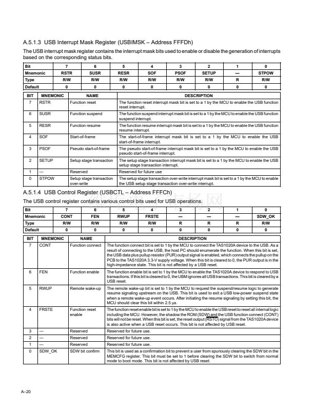
The USB control register contains various control bits used for USB operations.
鈥?/div>
R
0
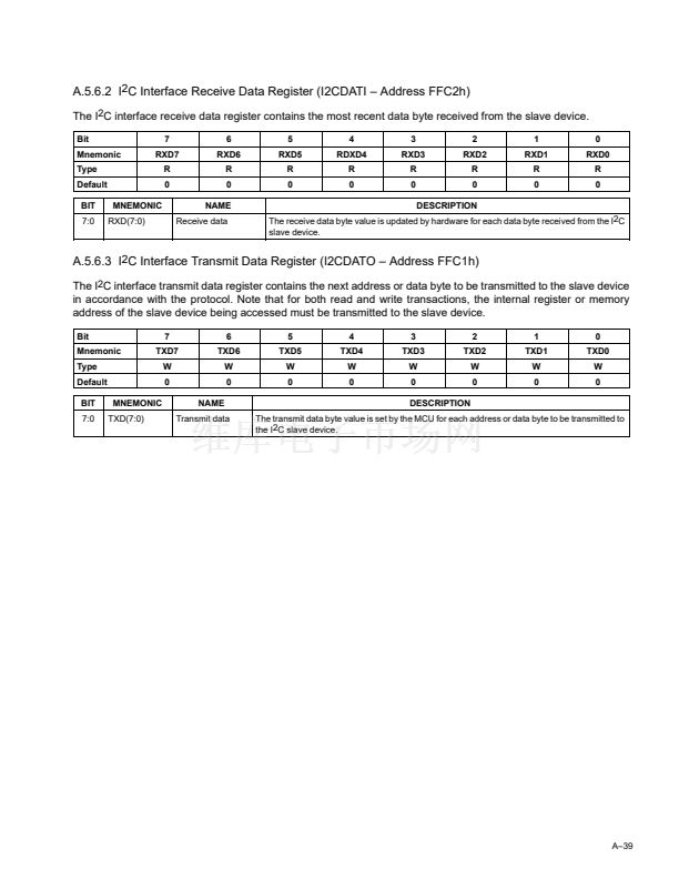
DESCRIPTION
The function connect bit is set to 1 by the MCU to connect the TAS1020A device to the USB. As a
result of connecting to the USB, the host PC should enumerate the function. When this bit is set,
the USB data plus pullup resistor (PUR) output signal is enabled, which connects the pullup on the
PCB to the TAS1020A 3.3-V supply voltage. When this bit is cleared to 0, the PUR output is in the
high-impedance state. This bit is not affected by a USB reset.
The function enable bit is set to 1 by the MCU to enable the TAS1020A device to respond to USB
transactions. If this bit is cleared to 0, the UBM ignores all USB transactions. This bit is cleared by a
USB reset.
The remote wake-up bit is set to 1 by the MCU to request the suspend/resume logic to generate
resume signaling upstream on the USB. This bit is used to exit a USB low-power suspend state
when a remote wake-up event occurs. After initiating the resume signaling by setting this bit, the
MCU should clear this bit within 2.5
碌s.
The function reset enable bit is set to 1 by the MCU to enable the USB reset to reset all internal logic
including the MCU. However, the shadow the ROM (SDW) and the USB function connect (CONT)
bits will not be reset. When this bit is set, the reset output (RSTO) signal from the TAS1020A device
is also active when a USB reset occurs. This bit is not affected by USB reset.
Reserved for future use.
Reserved for future use.
Reserved for future use.
This bit is used as a confirmation bit to prevent a user from spuriously clearing the SDW bit in the
MEMCFG register. This bit must be set to 1 before clearing the SDW bit to switch from normal
mode to boot mode. This bit is not affected by USB reset.
2
鈥?/div>
R
0
1
鈥?/div>
R
0
0
SDW_OK
R/W
0
6
FEN
Function enable
5
RWUP
Remote wake-up
4
FRSTE
Function reset
enable
3
2
1
0
鈥?/div>
鈥?/div>
鈥?/div>
SDW_OK
Reserved
Reserved
Reserved
SDW bit confirm
A鈥?0


 1
1
 2
2
 3
3
 4
4
 5
5
 6
6
 7
7
 8
8
 9
9
 10
10
 11
11
 12
12
 13
13
 14
14
 15
15
 16
16
 17
17
 18
18
 19
19
 20
20
 21
21
 22
22
 23
23
 24
24
 25
25
 26
26
 27
27
 28
28
 29
29
 30
30
 31
31
 32
32
 33
33
 34
34
 35
35
 36
36
 37
37
 38
38
 39
39
 40
40
 41
41
 42
42
 43
43
 44
44
 45
45
 46
46
 47
47
 48
48
 49
49
 50
50
 51
51
 52
52
 53
53
 54
54
 55
55
 56
56
 57
57
 58
58
 59
59
 60
60
 61
61
 62
62
 63
63
 64
64
 65
65
 66
66
 67
67
 68
68
 69
69
 70
70
 71
71
 72
72
 73
73
 74
74
 75
75
 76
76
 77
77
 78
78
 79
79
 80
80
 81
81
 82
82
 83
83
 84
84
 85
85
 86
86
 87
87
 88
88
 89
89
 90
90
 91
91
 92
92
 93
93
 94
94
 95
95
 96
96
 97
97
 98
98
 99
99
 100
100
 101
101
 102
102
 103
103
 104
104
 105
105
 106
106
 107
107
 108
108
 109
109
 110
110
 111
111
 112
112
 113
113
 114
114
