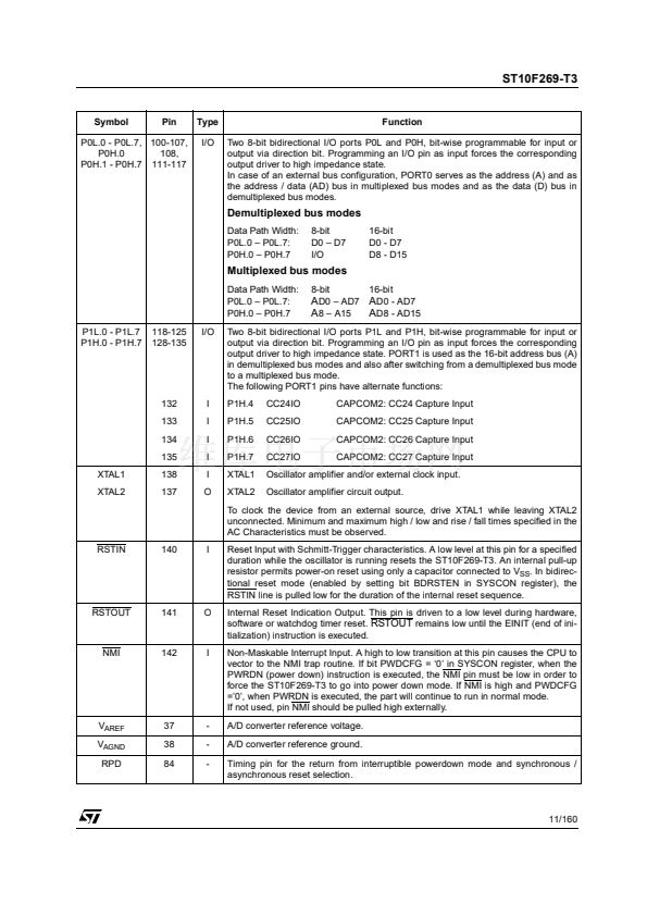
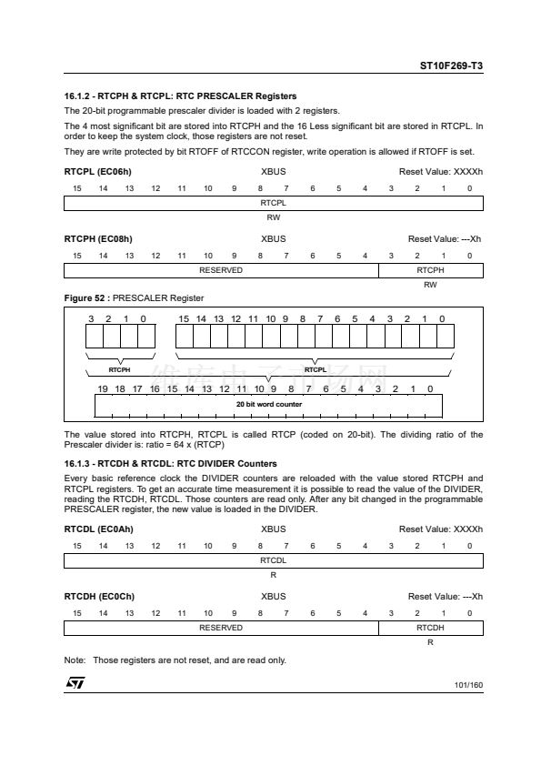
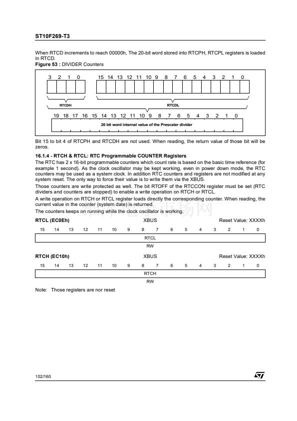
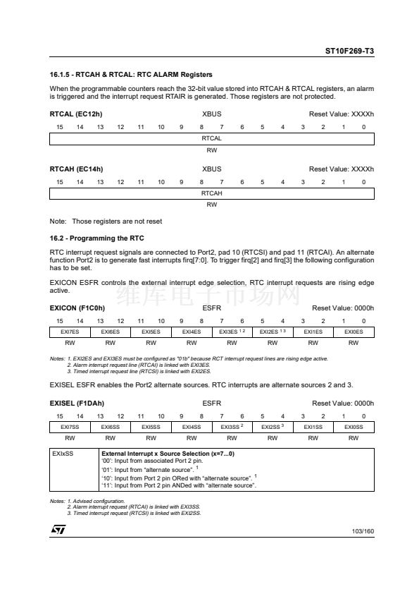
ST10F269-T3
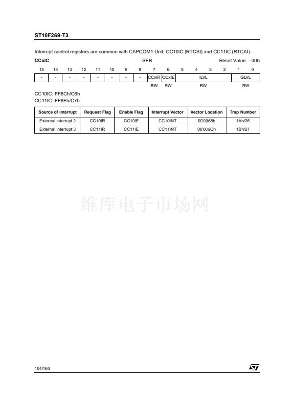
16.1 - RTC registers
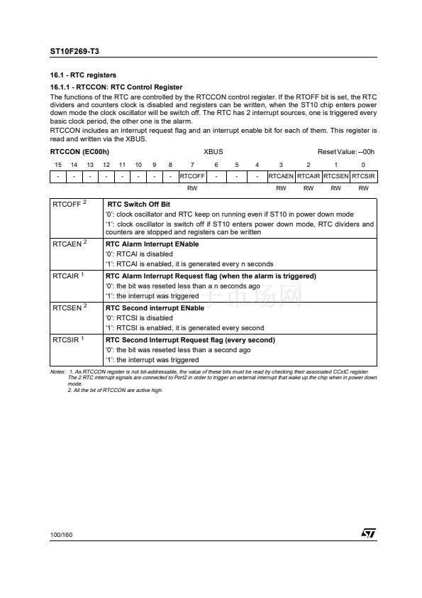
16.1.1 - RTCCON: RTC Control Register
The functions of the RTC are controlled by the RTCCON control register. If the RTOFF bit is set, the RTC
dividers and counters clock is disabled and registers can be written, when the ST10 chip enters power
down mode the clock oscillator will be switch off. The RTC has 2 interrupt sources, one is triggered every
basic clock period, the other one is the alarm.
RTCCON includes an interrupt request flag and an interrupt enable bit for each of them. This register is
read and written via the XBUS.
RTCCON (EC00h)
15
-
14
-
13
-
12
-
11
-
10
-
9
-
8
-
7
RTCOFF
RW
XBUS
6
-
5
-
4
-
3
2
Reset Value: --00h
1
0
RTCAEN RTCAIR RTCSEN RTCSIR
RW
RW
RW
RW
RTCOFF
2
RTC Switch Off Bit
鈥?鈥? clock oscillator and RTC keep on running even if ST10 in power down mode
鈥?鈥? clock oscillator is switch off if ST10 enters power down mode, RTC dividers and
counters are stopped and registers can be written
RTC Alarm Interrupt ENable
鈥?鈥? RTCAI is disabled
鈥?鈥? RTCAI is enabled, it is generated every n seconds
RTC Alarm Interrupt Request flag (when the alarm is triggered)
鈥?鈥? the bit was reseted less than a n seconds ago
鈥?鈥? the interrupt was triggered
RTC Second interrupt ENable
鈥?鈥? RTCSI is disabled
鈥?鈥? RTCSI is enabled, it is generated every second
RTC Second Interrupt Request flag (every second)
鈥?鈥? the bit was reseted less than a second ago
鈥?鈥? the interrupt was triggered
RTCAEN
2
RTCAIR
1
RTCSEN
2
RTCSIR
1
Notes: 1. As RTCCON register is not bit-addressable, the value of these bits must be read by checking their associated CCxIC register.
The 2 RTC interrupt signals are connected to Port2 in order to trigger an external interrupt that wake up the chip when in power down
mode.
2. All the bit of RTCCON are active high.
100/160


 1
1
 2
2
 3
3
 4
4
 5
5
 6
6
 7
7
 8
8
 9
9
 10
10
 11
11
 12
12
 13
13
 14
14
 15
15
 16
16
 17
17
 18
18
 19
19
 20
20
 21
21
 22
22
 23
23
 24
24
 25
25
 26
26
 27
27
 28
28
 29
29
 30
30
 31
31
 32
32
 33
33
 34
34
 35
35
 36
36
 37
37
 38
38
 39
39
 40
40
 41
41
 42
42
 43
43
 44
44
 45
45
 46
46
 47
47
 48
48
 49
49
 50
50
 51
51
 52
52
 53
53
 54
54
 55
55
 56
56
 57
57
 58
58
 59
59
 60
60
 61
61
 62
62
 63
63
 64
64
 65
65
 66
66
 67
67
 68
68
 69
69
 70
70
 71
71
 72
72
 73
73
 74
74
 75
75
 76
76
 77
77
 78
78
 79
79
 80
80
 81
81
 82
82
 83
83
 84
84
 85
85
 86
86
 87
87
 88
88
 89
89
 90
90
 91
91
 92
92
 93
93
 94
94
 95
95
 96
96
 97
97
 98
98
 99
99
 100
100
 101
101
 102
102
 103
103
 104
104
 105
105
 106
106
 107
107
 108
108
 109
109
 110
110
 111
111
 112
112
 113
113
 114
114
 115
115
 116
116
 117
117
 118
118
 119
119
 120
120
 121
121
 122
122
 123
123
 124
124
 125
125
 126
126
 127
127
 128
128
 129
129
 130
130
 131
131
 132
132
 133
133
 134
134
 135
135
 136
136
 137
137
 138
138
 139
139
 140
140
 141
141
 142
142
 143
143
 144
144
 145
145
 146
146
 147
147
 148
148
 149
149
 150
150
 151
151
 152
152
 153
153
 154
154
 155
155
 156
156
 157
157
 158
158
 159
159
 160
160
