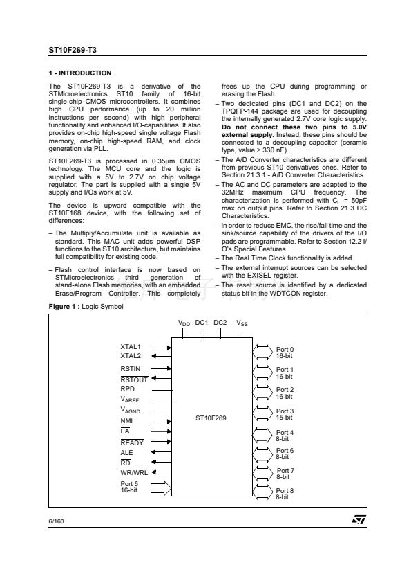
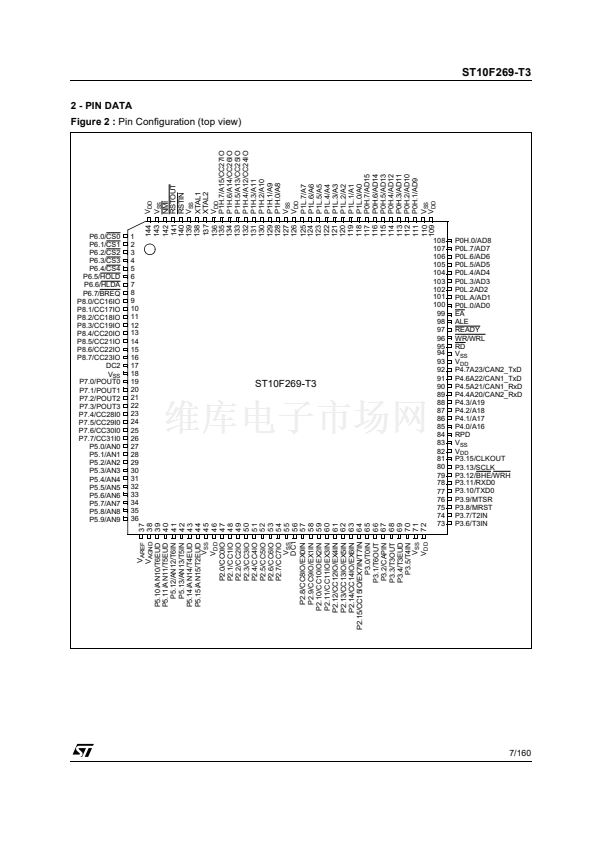
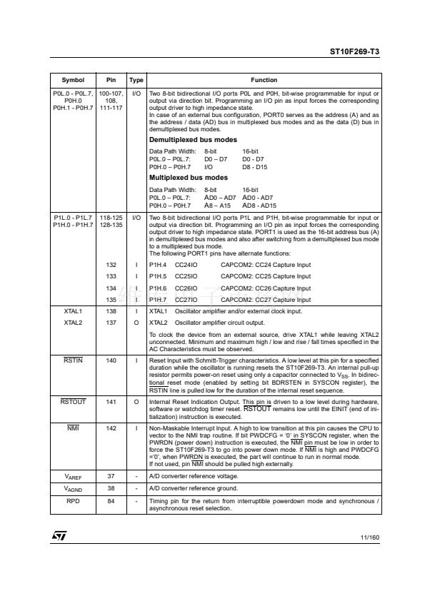
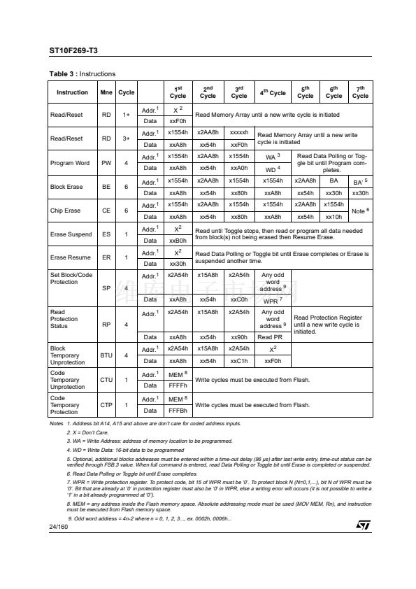
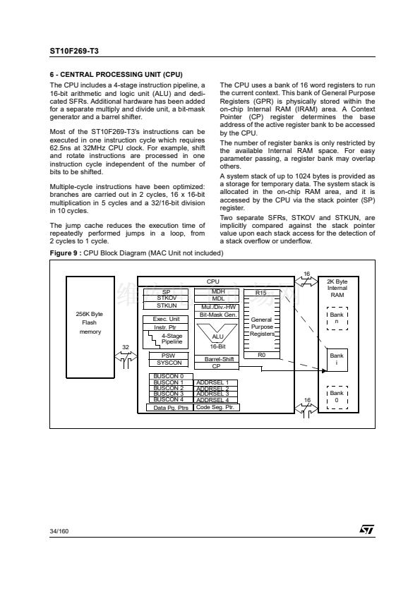
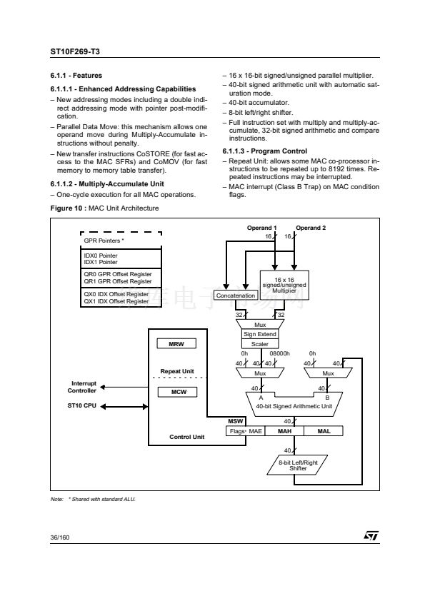
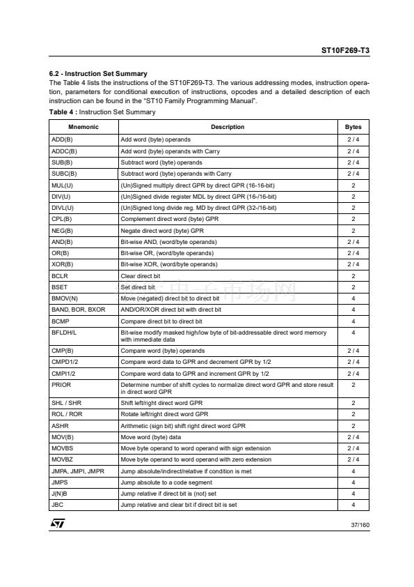
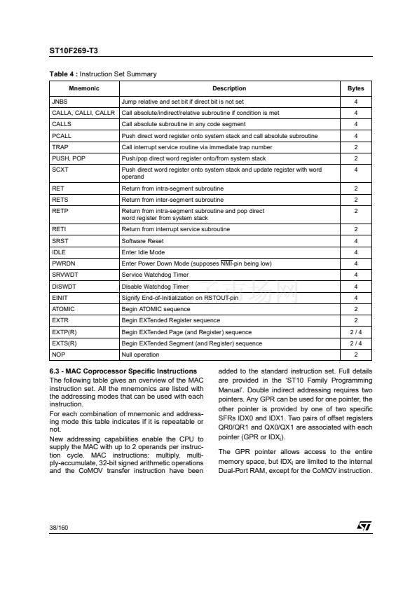
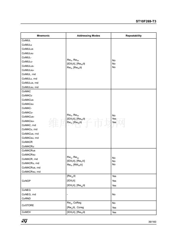
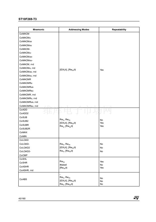
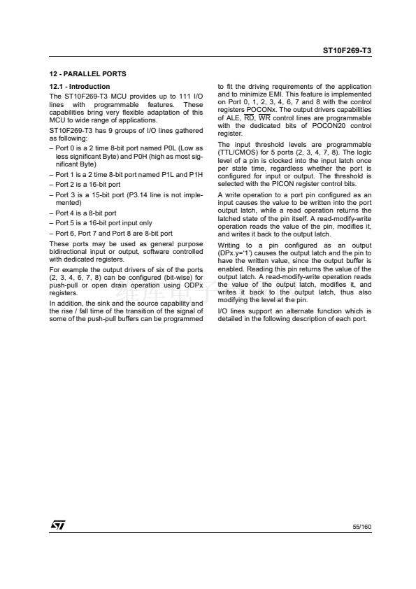
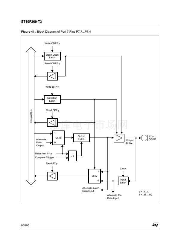
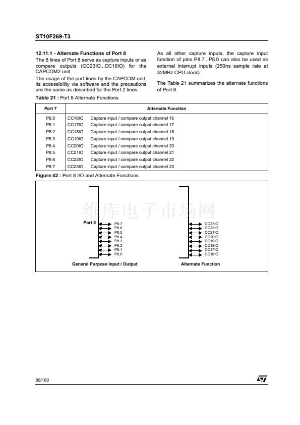
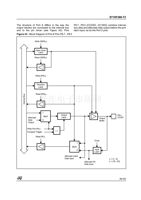
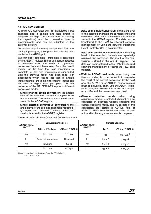
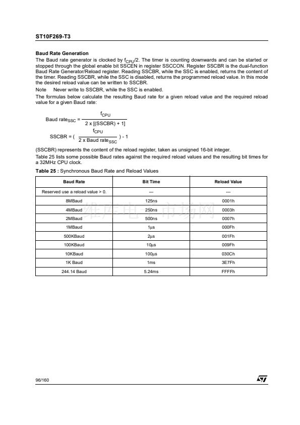
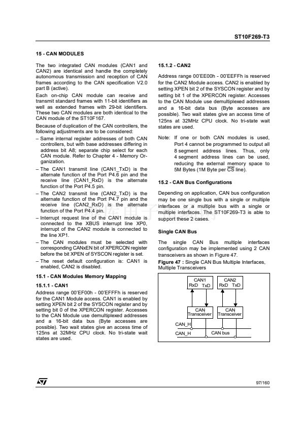
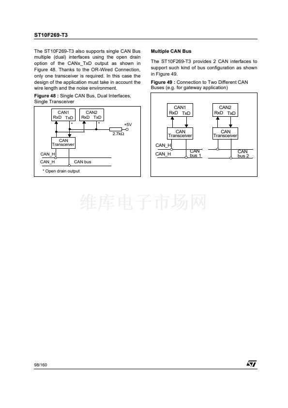
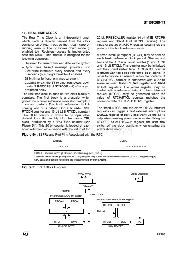
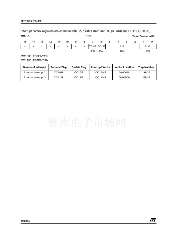
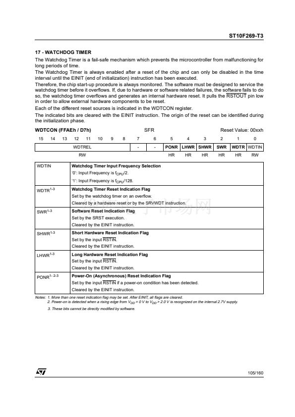
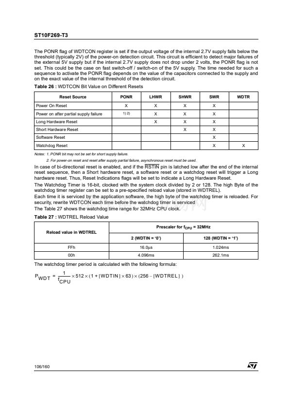
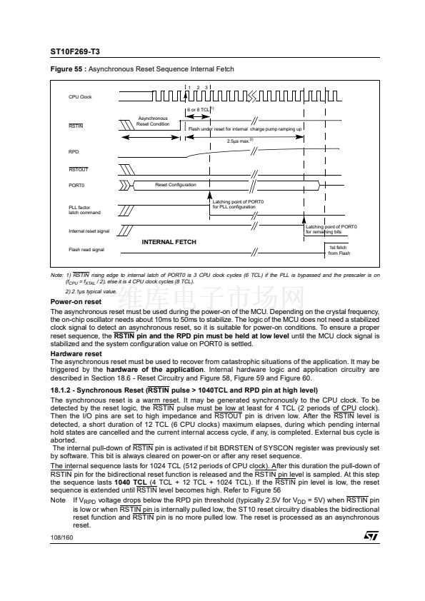
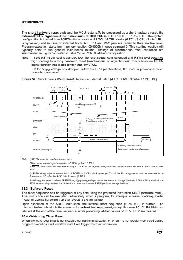
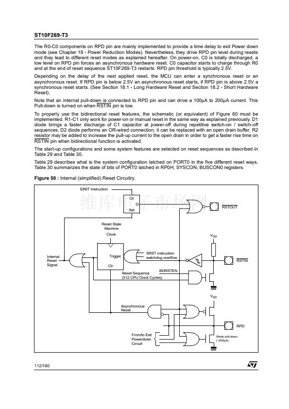
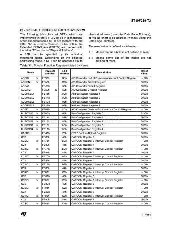
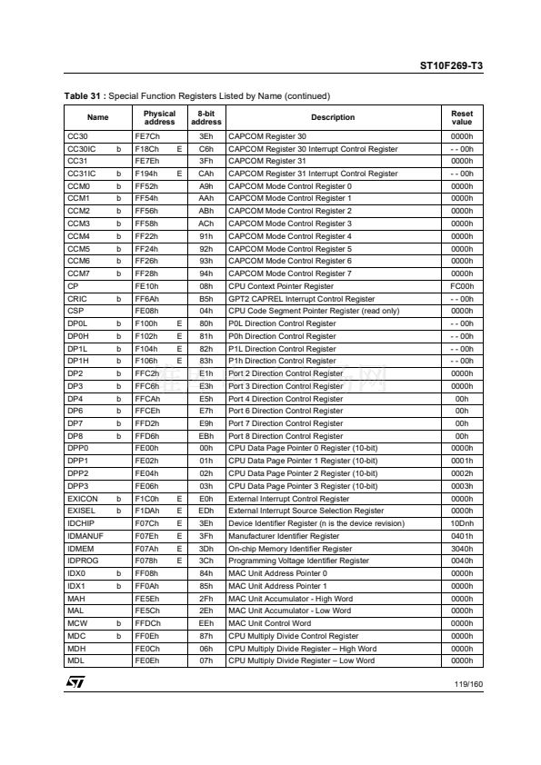
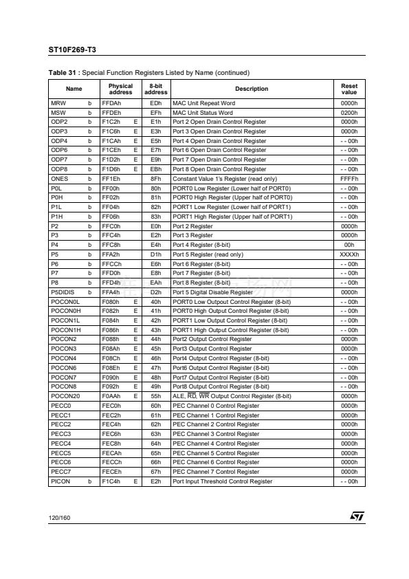
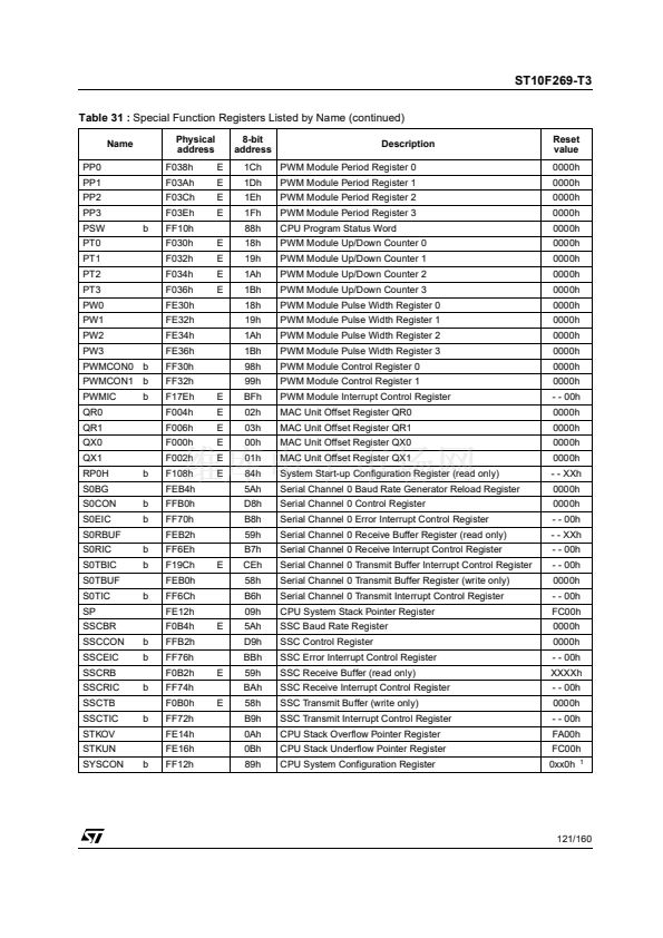
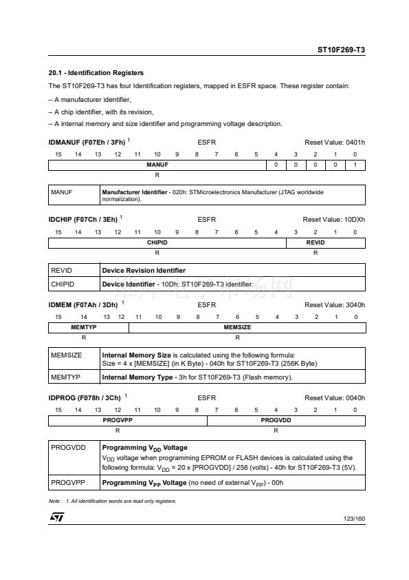
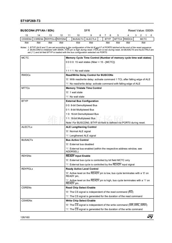
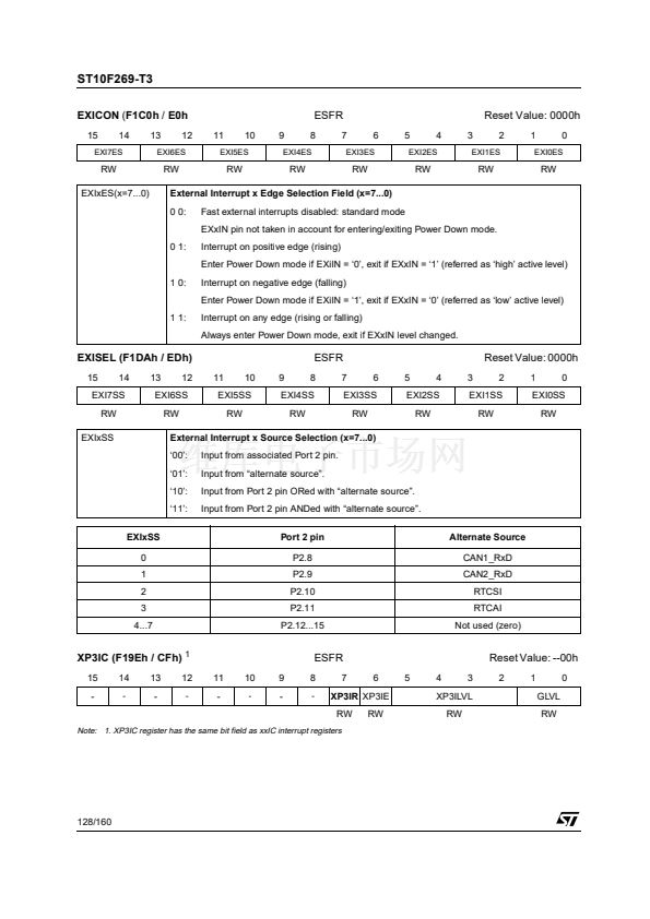
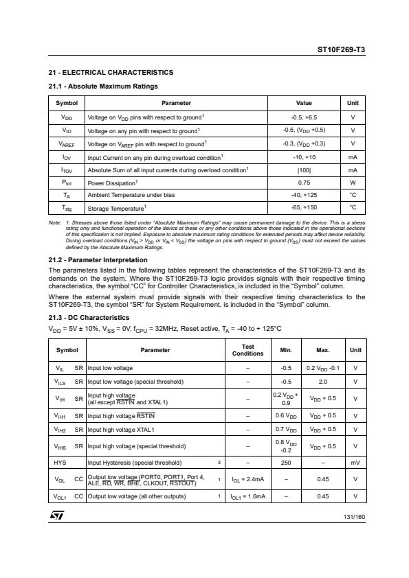
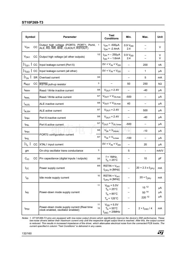
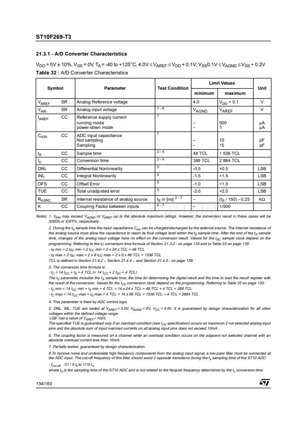
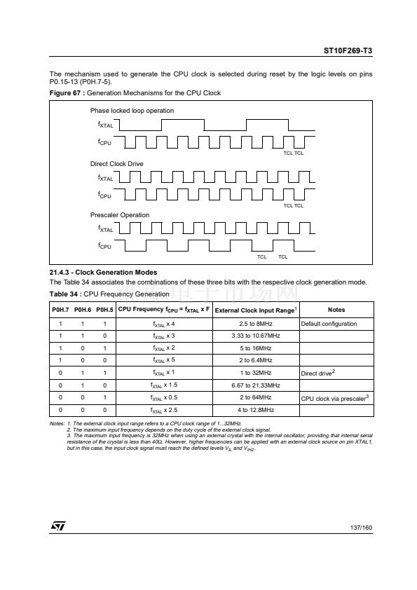
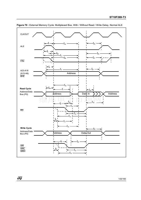
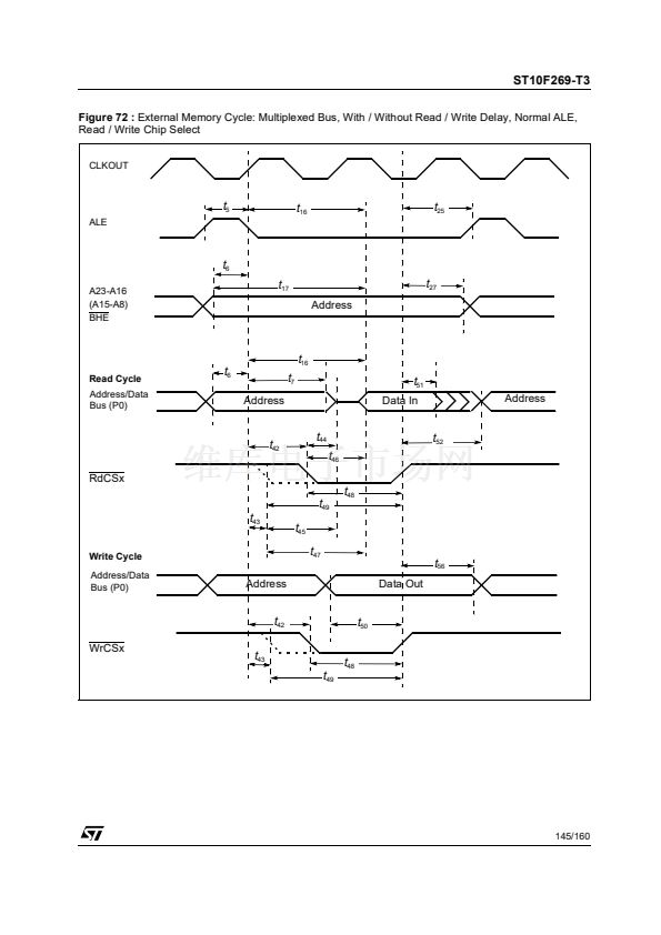
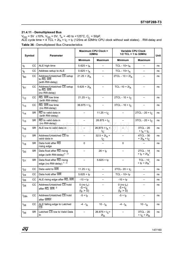
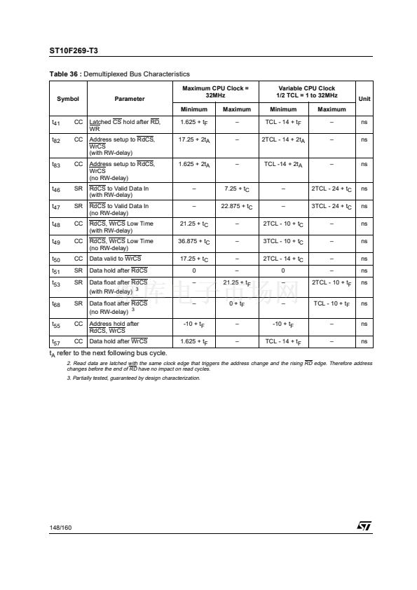
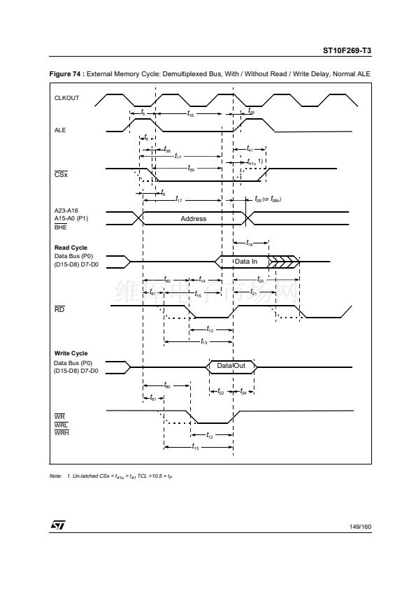
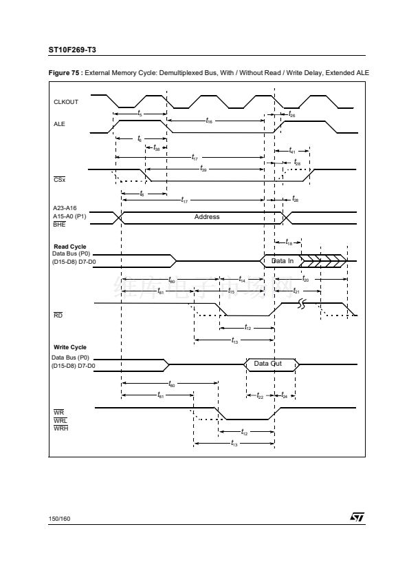
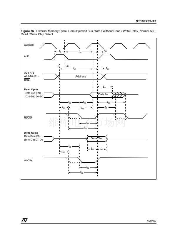
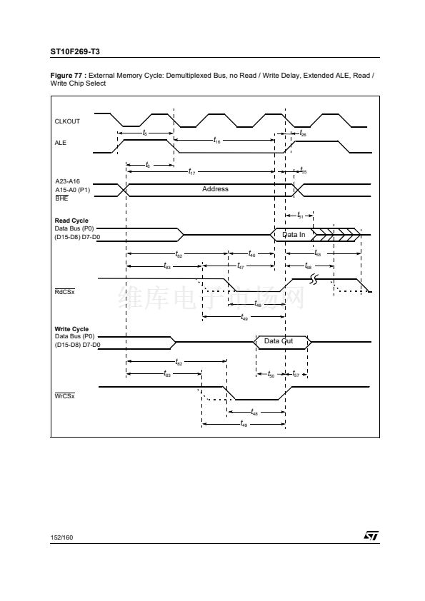
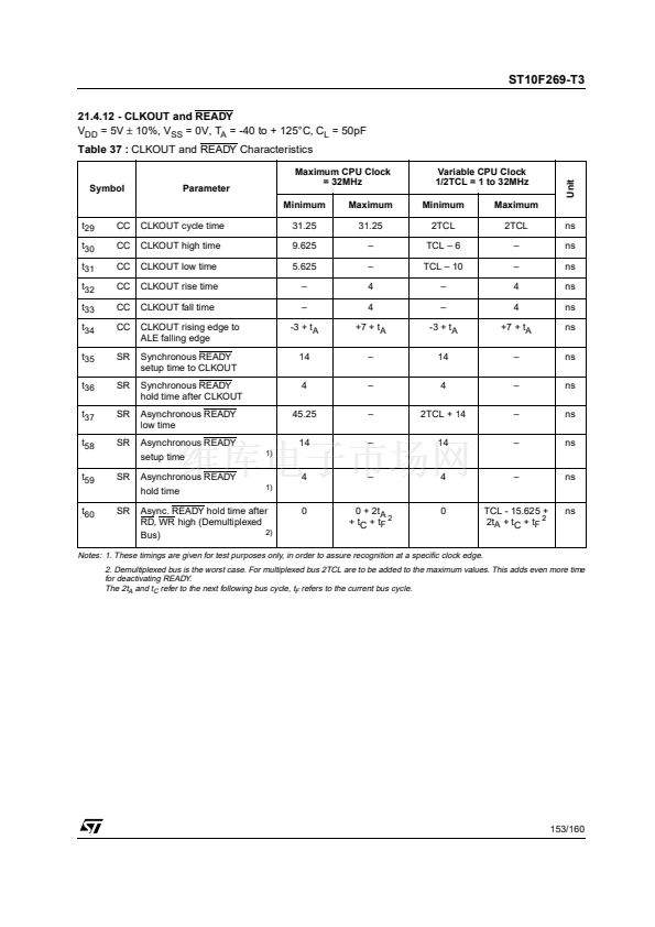
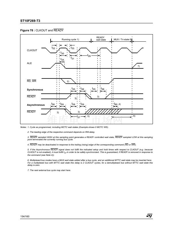
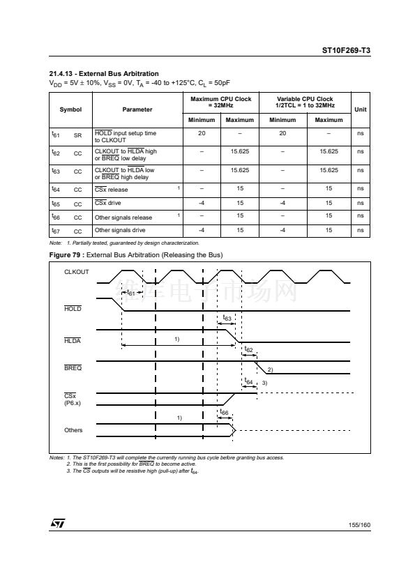
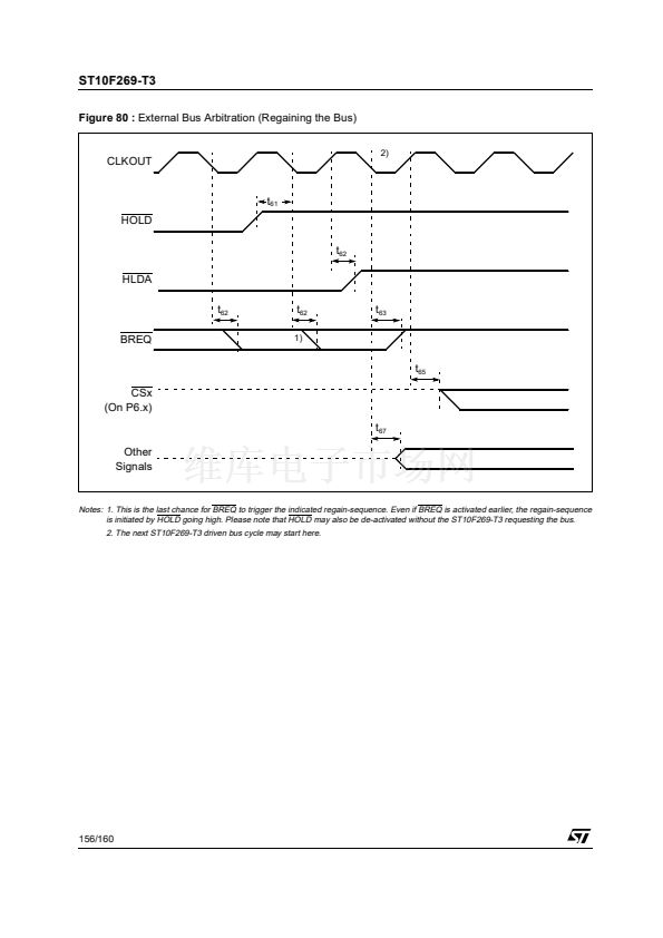
ST10F269-T3
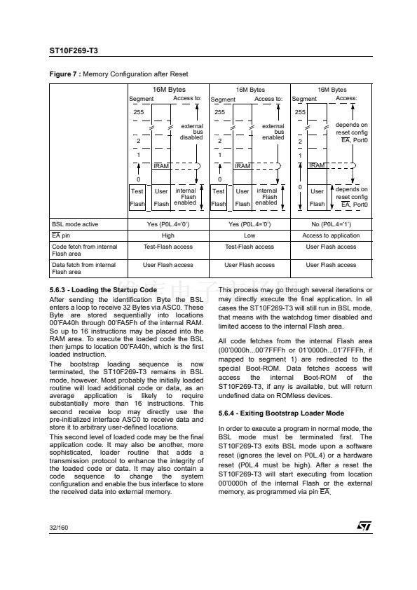
Figure 7 :
Memory Configuration after Reset
16M Bytes
Segment
255
external
bus
disabled
Access to:
Segment
255
external
bus
enabled
16M Bytes
Access to:
16M Bytes
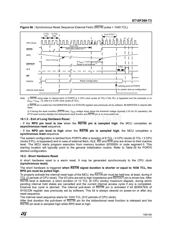
Access:
Segment
255
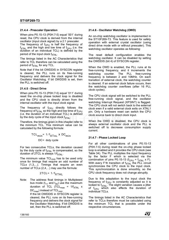
depends on
reset config
EA, Port0
2
1
IRAM
0
Test
Flash
BSL mode active
EA pin
Code fetch from internal
Flash area
Data fetch from internal
Flash area
2
1
IRAM
0
2
1
IRAM
internal
Flash
enabled
Flash
User
Yes (P0L.4=鈥?鈥?
High
Test
Flash
internal
Flash
enabled
Flash
User
Yes (P0L.4=鈥?鈥?
Low
0
User
Flash
depends on
reset config
EA, Port0
No (P0L.4=鈥?鈥?
Access to application
User Flash access
User Flash access
Test-Flash access
User Flash access
Test-Flash access
User Flash access
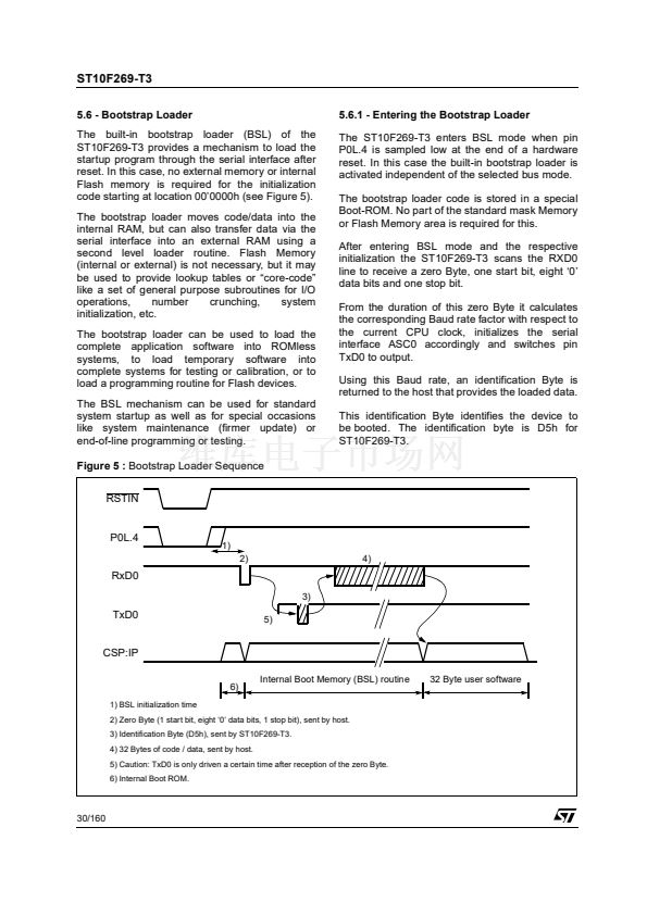
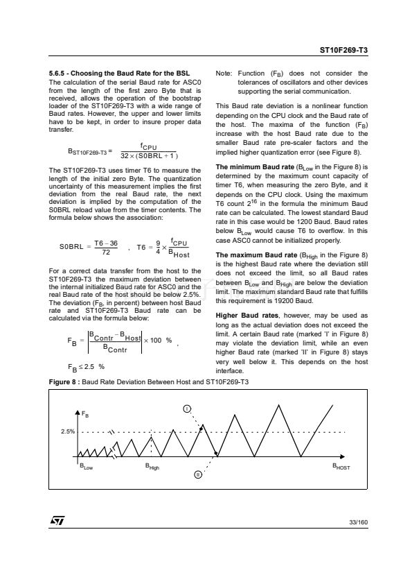
5.6.3 - Loading the Startup Code
After sending the identification Byte the BSL
enters a loop to receive 32 Bytes via ASC0. These
Byte are stored sequentially into locations
00鈥橣A40h through 00鈥橣A5Fh of the internal RAM.
So up to 16 instructions may be placed into the
RAM area. To execute the loaded code the BSL
then jumps to location 00鈥橣A40h, which is the first
loaded instruction.
The bootstrap loading sequence is now
terminated, the ST10F269-T3 remains in BSL
mode, however. Most probably the initially loaded
routine will load additional code or data, as an
average application is likely to require
substantially more than 16 instructions. This
second receive loop may directly use the
pre-initialized interface ASC0 to receive data and
store it to arbitrary user-defined locations.
This second level of loaded code may be the final
application code. It may also be another, more
sophisticated, loader routine that adds a
transmission protocol to enhance the integrity of
the loaded code or data. It may also contain a
code sequence to change the system
configuration and enable the bus interface to store
the received data into external memory.
This process may go through several iterations or
may directly execute the final application. In all
cases the ST10F269-T3 will still run in BSL mode,
that means with the watchdog timer disabled and
limited access to the internal Flash area.
All code fetches from the internal Flash area
(00鈥?000h...00鈥?FFFh or 01鈥?000h...01鈥?FFFh, if
mapped to segment 1) are redirected to the
special Boot-ROM. Data fetches access will
access the internal Boot-ROM of the
ST10F269-T3, if any is available, but will return
undefined data on ROMless devices.
5.6.4 - Exiting Bootstrap Loader Mode
In order to execute a program in normal mode, the
BSL mode must be terminated first. The
ST10F269-T3 exits BSL mode upon a software
reset (ignores the level on P0L.4) or a hardware
reset (P0L.4 must be high). After a reset the
ST10F269-T3 will start executing from location
00鈥?000h of the internal Flash or the external
memory, as programmed via pin EA.
32/160


 1
1
 2
2
 3
3
 4
4
 5
5
 6
6
 7
7
 8
8
 9
9
 10
10
 11
11
 12
12
 13
13
 14
14
 15
15
 16
16
 17
17
 18
18
 19
19
 20
20
 21
21
 22
22
 23
23
 24
24
 25
25
 26
26
 27
27
 28
28
 29
29
 30
30
 31
31
 32
32
 33
33
 34
34
 35
35
 36
36
 37
37
 38
38
 39
39
 40
40
 41
41
 42
42
 43
43
 44
44
 45
45
 46
46
 47
47
 48
48
 49
49
 50
50
 51
51
 52
52
 53
53
 54
54
 55
55
 56
56
 57
57
 58
58
 59
59
 60
60
 61
61
 62
62
 63
63
 64
64
 65
65
 66
66
 67
67
 68
68
 69
69
 70
70
 71
71
 72
72
 73
73
 74
74
 75
75
 76
76
 77
77
 78
78
 79
79
 80
80
 81
81
 82
82
 83
83
 84
84
 85
85
 86
86
 87
87
 88
88
 89
89
 90
90
 91
91
 92
92
 93
93
 94
94
 95
95
 96
96
 97
97
 98
98
 99
99
 100
100
 101
101
 102
102
 103
103
 104
104
 105
105
 106
106
 107
107
 108
108
 109
109
 110
110
 111
111
 112
112
 113
113
 114
114
 115
115
 116
116
 117
117
 118
118
 119
119
 120
120
 121
121
 122
122
 123
123
 124
124
 125
125
 126
126
 127
127
 128
128
 129
129
 130
130
 131
131
 132
132
 133
133
 134
134
 135
135
 136
136
 137
137
 138
138
 139
139
 140
140
 141
141
 142
142
 143
143
 144
144
 145
145
 146
146
 147
147
 148
148
 149
149
 150
150
 151
151
 152
152
 153
153
 154
154
 155
155
 156
156
 157
157
 158
158
 159
159
 160
160
