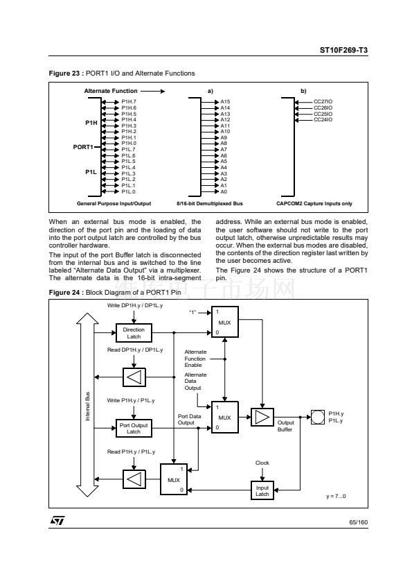
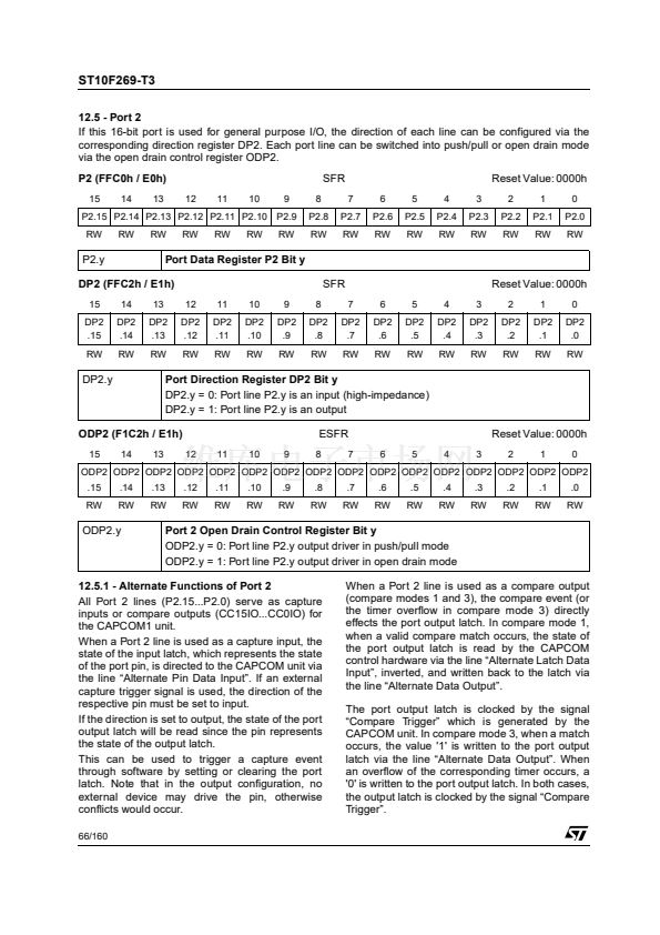
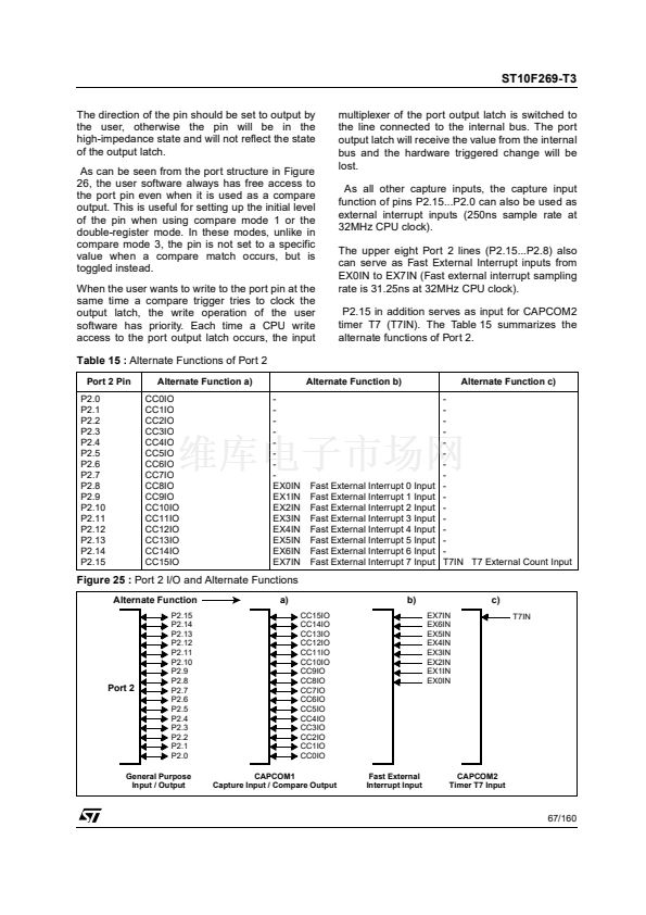
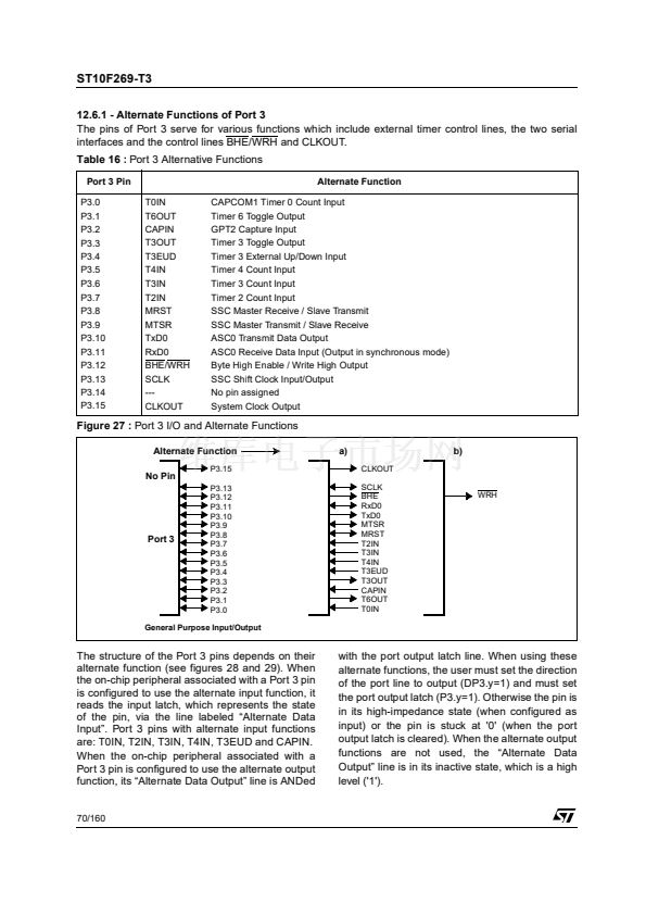
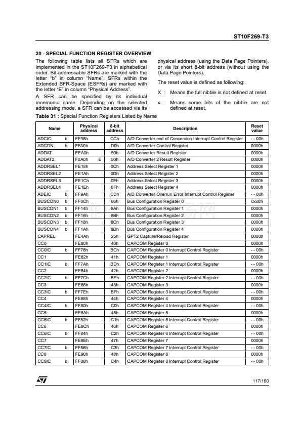
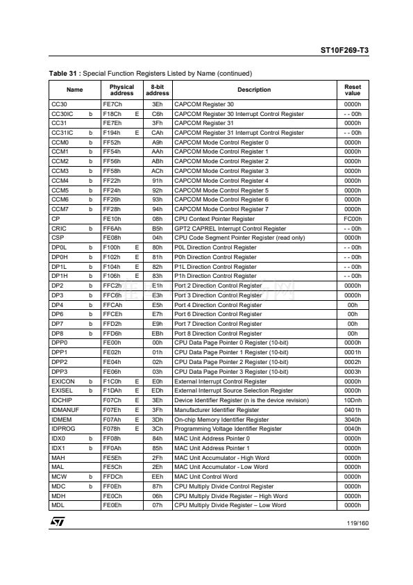
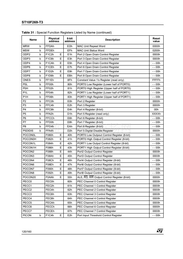
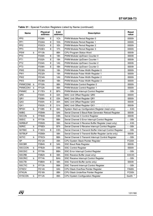
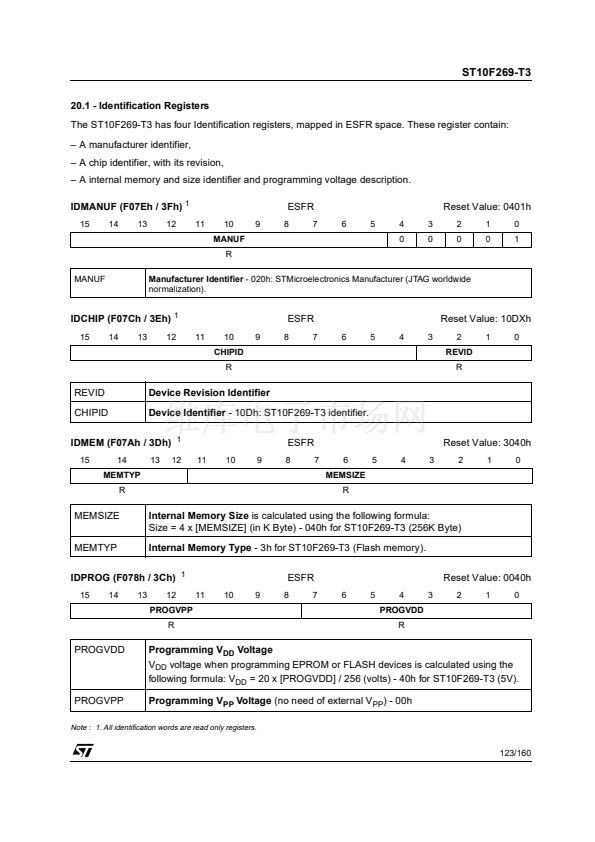
ST10F269-T3
The System Configuration Register SYSCON
This bit-addressable register provides general system configuration and control functions. The reset
value for register SYSCON depends on the state of the PORT0 pins during reset.
SYSCON (FF12h / 89h)
15
14
STKSZ
SFR
11
SGT
DIS
Reset Value: 0xx0h
7
6
CS
CFG
13
12
ROM
S1
10
ROM
EN
9
BYT
DIS
8
CLK
EN
5
PWD
CFG
4
OWD
DIS
3
BDR
STEN
2
XPEN
1
VISI
BLE
0
XPER-
SHARE
WR
CFG
RW
RW
RW
RW
1
RW
1
RW
RW
1
RW
RW
RW
RW
RW
RW
RW
Notes: 1. These bits are set directly or indirectly according to PORT0 and EA pin configuration during reset sequence.
2. Register SYSCON cannot be changed after execution of the EINIT instruction.
Bit
XPEN
0
1
BDRSTEN
0
1
OWDDIS
0
XBUS Peripheral Enable Bit
Function
Accesses to the on-chip X-Peripherals and their functions are disabled
The on-chip X-Peripherals are enabled and can be accessed.
Bidirectional Reset Enable
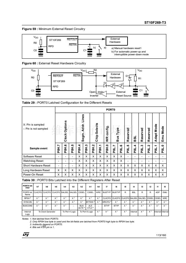
RSTIN pin is an input pin only. SW Reset or WDT Reset have no effect on this pin
RSTIN pin is a bidirectional pin. This pin is pulled low during 1024 TCL during reset sequence.
Oscillator Watchdog Disable Control
Oscillator Watchdog (OWD) is enabled. If PLL is bypassed, the OWD monitors XTAL1 activity. If
there is no activity on XTAL1 for at least 1
碌s,
the CPU clock is switched automatically to PLL鈥檚
base frequency (2 to 10MHz).
OWD is disabled. If the PLL is bypassed, the CPU clock is always driven by XTAL1 signal. The
PLL is turned off to reduce power supply current.
Power Down Mode Configuration Control
1
PWDCFG
0
Power Down Mode can only be entered during PWRDN instruction execution if NMI pin is low, oth-
erwise the instruction has no effect. To exit Power Down Mode, an external reset must occurs by
asserting the RSTIN pin.
Power Down Mode can only be entered during PWRDN instruction execution if all enabled fast
external interrupt EXxIN pins are in their inactive level. Exiting this mode can be done by asserting
one enabled EXxIN pin.
Chip Select Configuration Control
1
CSCFG
0
1
Latched Chip Select lines: CSx change 1 TCL after rising edge of ALE
Unlatched Chip Select lines: CSx change with rising edge of ALE
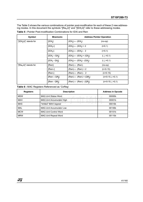
6.1 - Multiplier-accumulator Unit (MAC)
The MAC co-processor is a specialized co-pro-
cessor added to the ST10 CPU Core in order to
improve the performances of the ST10 Family in
signal processing algorithms.
Signal processing needs at least three specialized
units operating in parallel to achieve maximum
performance:
鈥?A Multiply-Accumulate Unit,
鈥?An Address Generation Unit, able to feed the
MAC Unit with 2 operands per cycle,
鈥?A Repeat Unit, to execute series of multiply-ac-
cumulate instructions.
The existing ST10 CPU has been modified to
include new addressing capabilities which enable
the CPU to supply the new co-processor with up
to 2 operands per instruction cycle.
This new co-processor (so-called MAC) contains
a fast multiply-accumulate unit and a repeat unit.
The co-processor instructions extend the ST10
CPU instruction set with multiply, multiply-accu-
mulate, 32-bit signed arithmetic operations.
A new transfer instruction CoMOV has also been
added to take benefit of the new addressing capa-
bilities.
35/160


 1
1
 2
2
 3
3
 4
4
 5
5
 6
6
 7
7
 8
8
 9
9
 10
10
 11
11
 12
12
 13
13
 14
14
 15
15
 16
16
 17
17
 18
18
 19
19
 20
20
 21
21
 22
22
 23
23
 24
24
 25
25
 26
26
 27
27
 28
28
 29
29
 30
30
 31
31
 32
32
 33
33
 34
34
 35
35
 36
36
 37
37
 38
38
 39
39
 40
40
 41
41
 42
42
 43
43
 44
44
 45
45
 46
46
 47
47
 48
48
 49
49
 50
50
 51
51
 52
52
 53
53
 54
54
 55
55
 56
56
 57
57
 58
58
 59
59
 60
60
 61
61
 62
62
 63
63
 64
64
 65
65
 66
66
 67
67
 68
68
 69
69
 70
70
 71
71
 72
72
 73
73
 74
74
 75
75
 76
76
 77
77
 78
78
 79
79
 80
80
 81
81
 82
82
 83
83
 84
84
 85
85
 86
86
 87
87
 88
88
 89
89
 90
90
 91
91
 92
92
 93
93
 94
94
 95
95
 96
96
 97
97
 98
98
 99
99
 100
100
 101
101
 102
102
 103
103
 104
104
 105
105
 106
106
 107
107
 108
108
 109
109
 110
110
 111
111
 112
112
 113
113
 114
114
 115
115
 116
116
 117
117
 118
118
 119
119
 120
120
 121
121
 122
122
 123
123
 124
124
 125
125
 126
126
 127
127
 128
128
 129
129
 130
130
 131
131
 132
132
 133
133
 134
134
 135
135
 136
136
 137
137
 138
138
 139
139
 140
140
 141
141
 142
142
 143
143
 144
144
 145
145
 146
146
 147
147
 148
148
 149
149
 150
150
 151
151
 152
152
 153
153
 154
154
 155
155
 156
156
 157
157
 158
158
 159
159
 160
160
