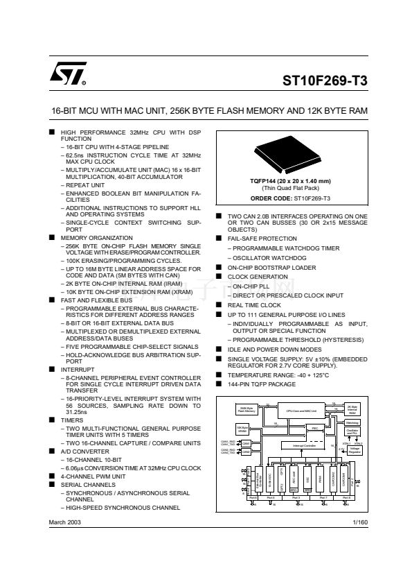
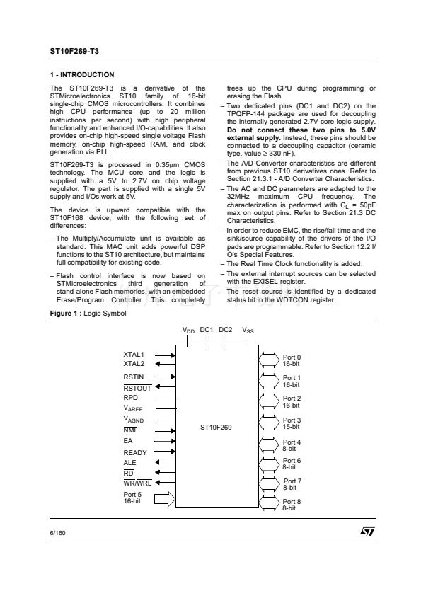
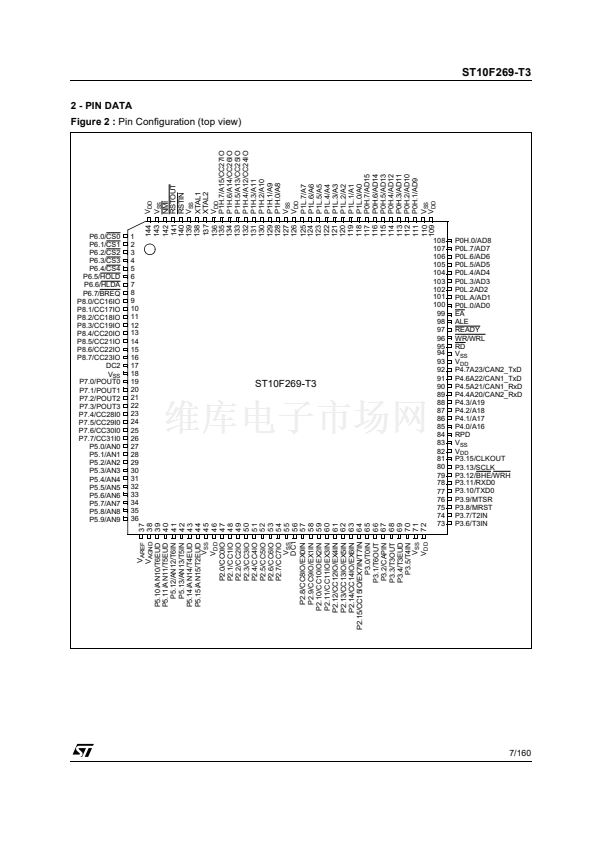
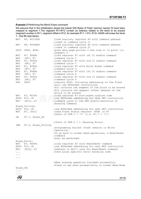
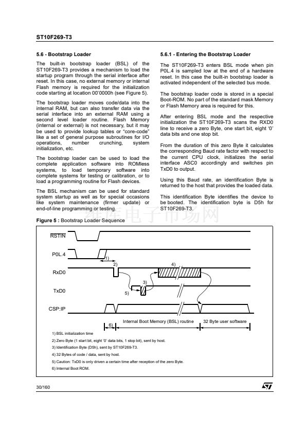
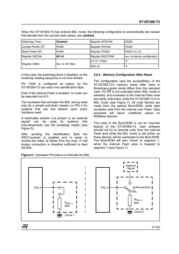
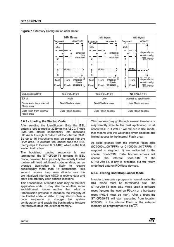
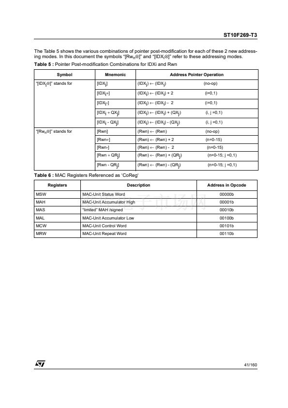
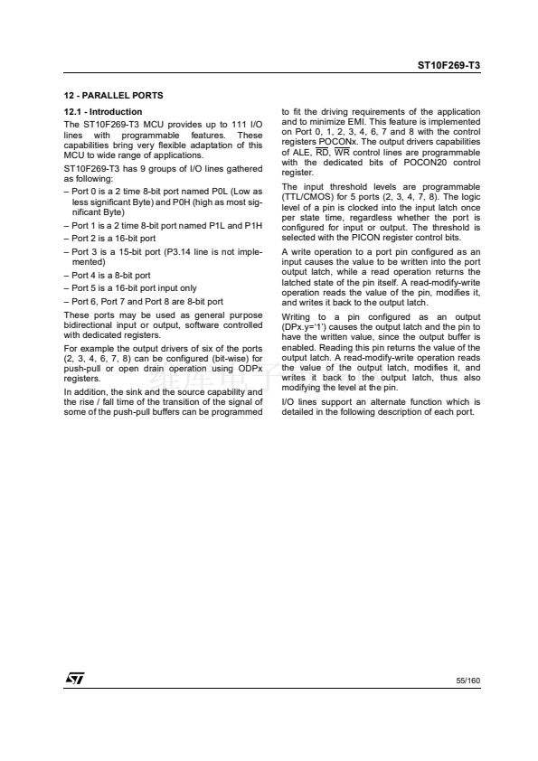
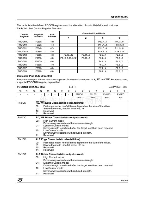
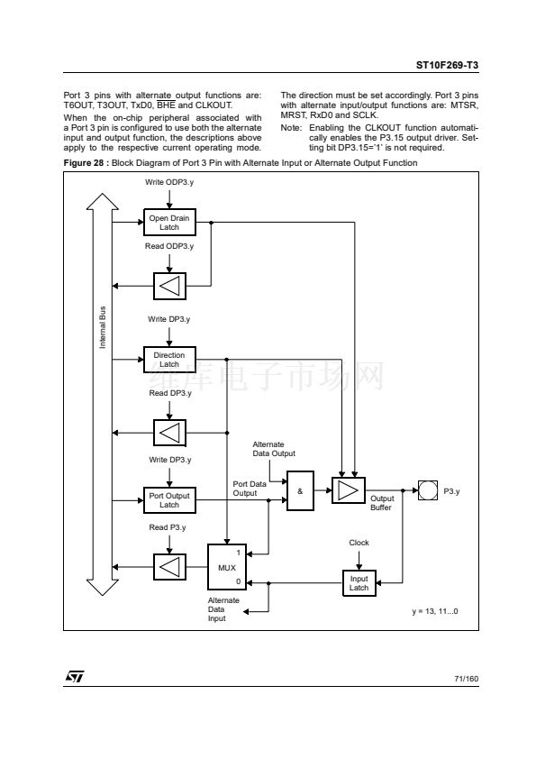
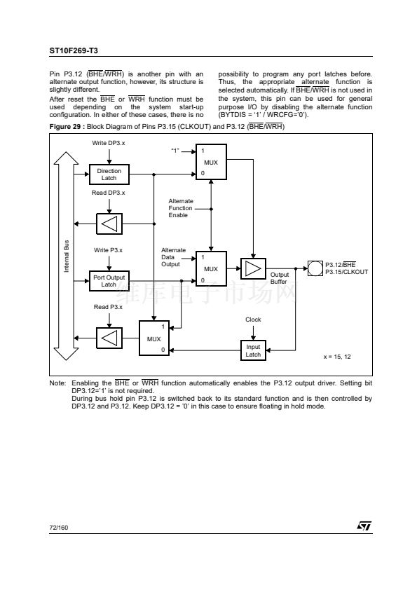
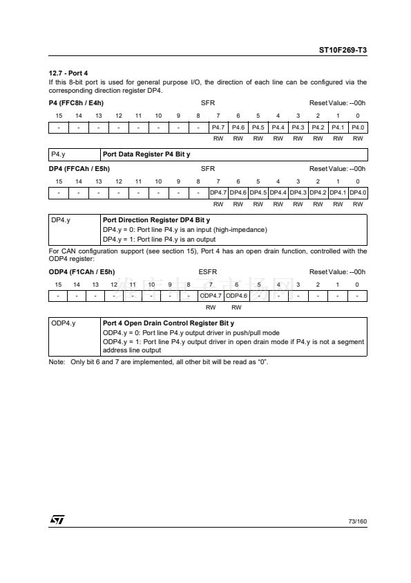
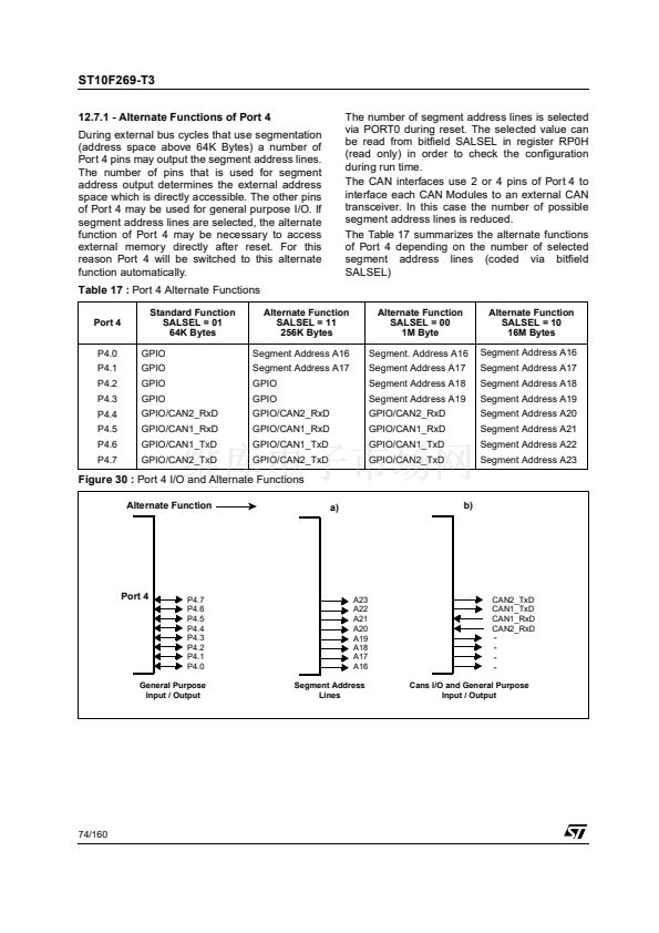
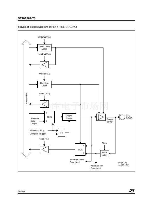
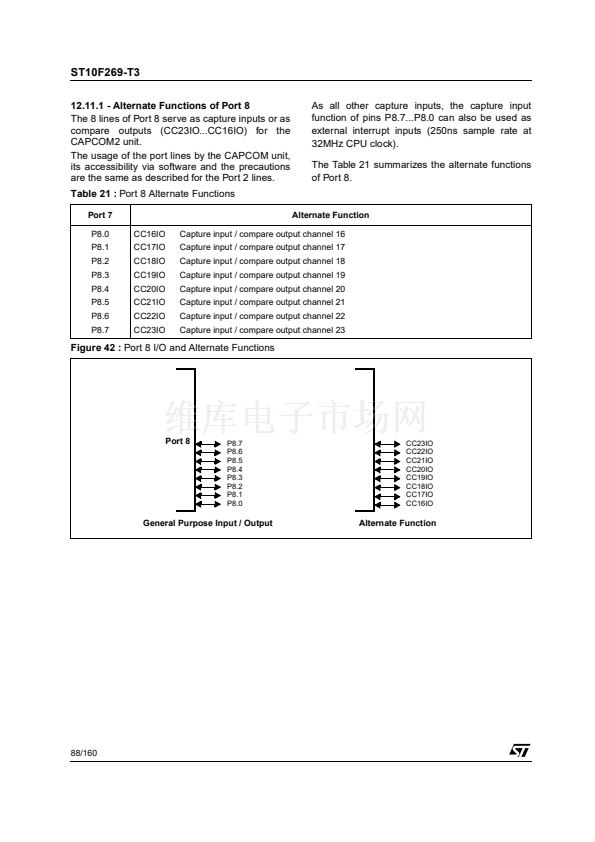
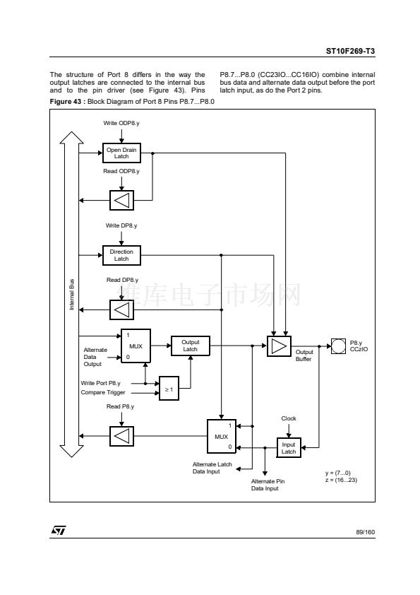
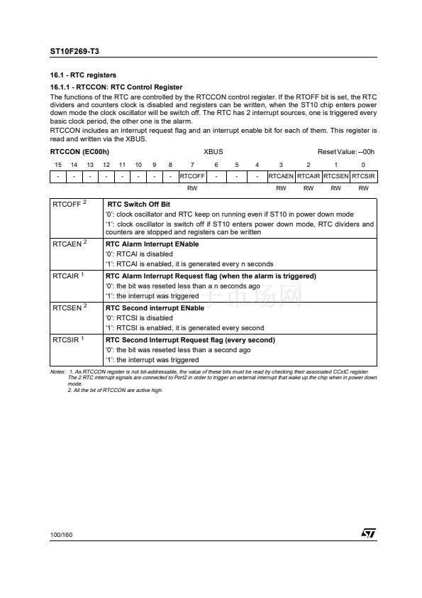
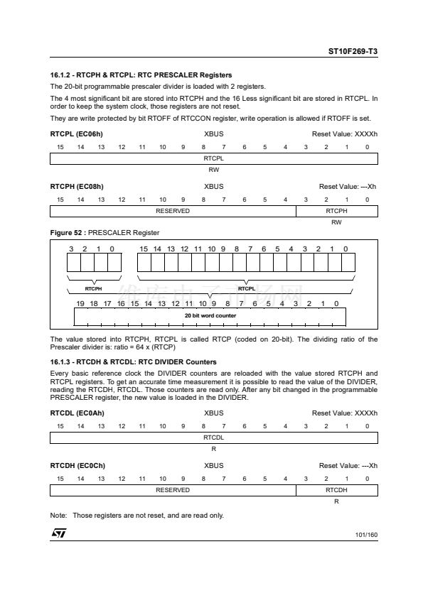
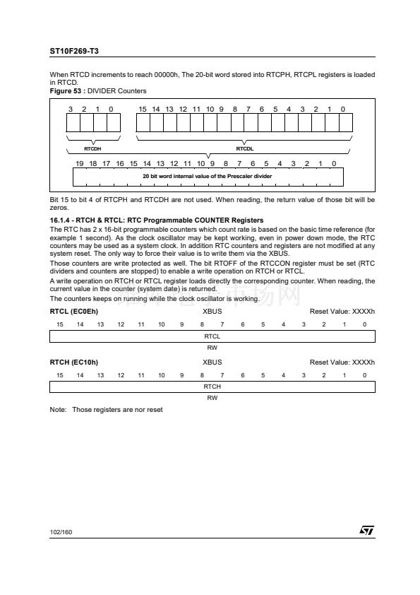
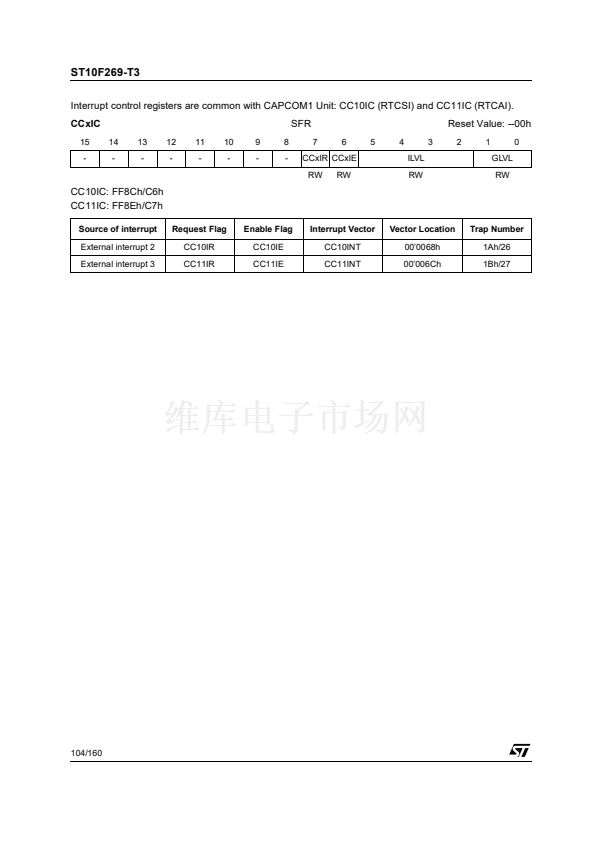
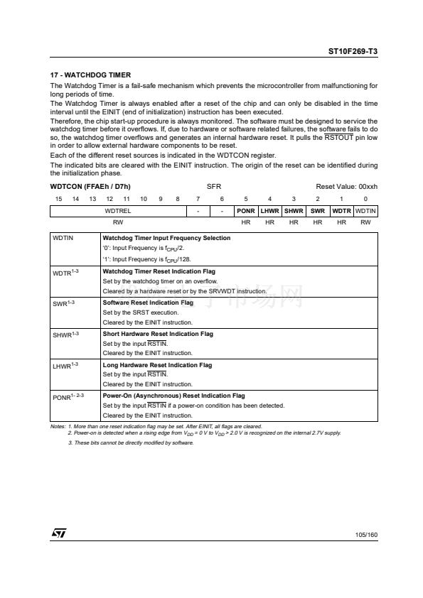
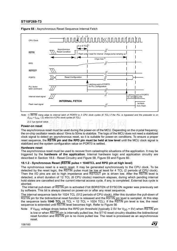
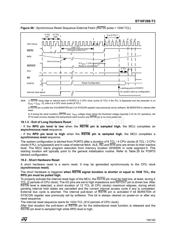
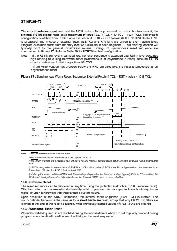
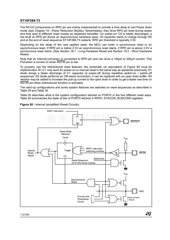
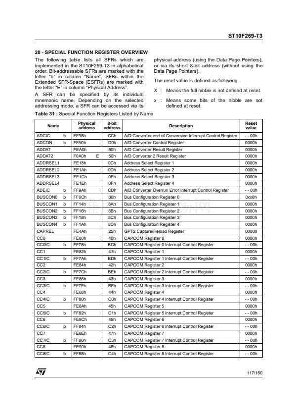
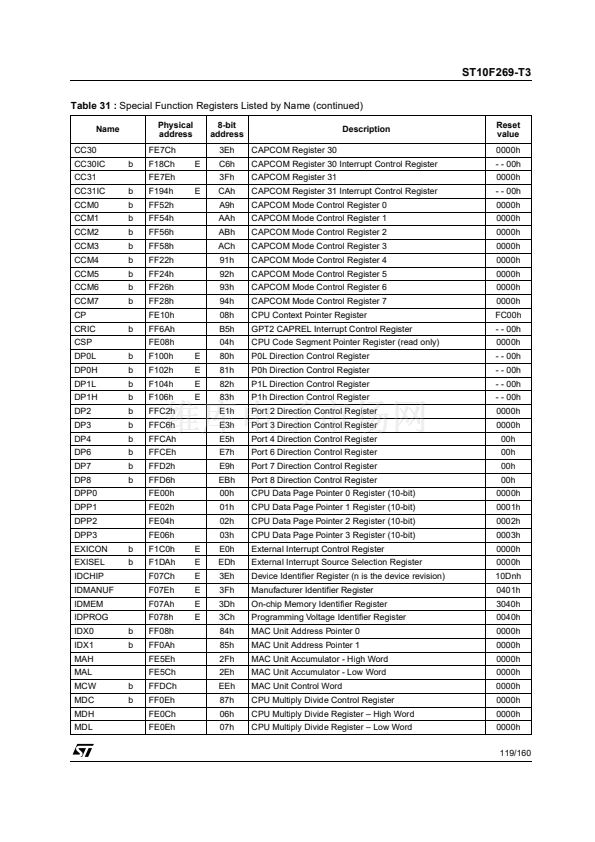
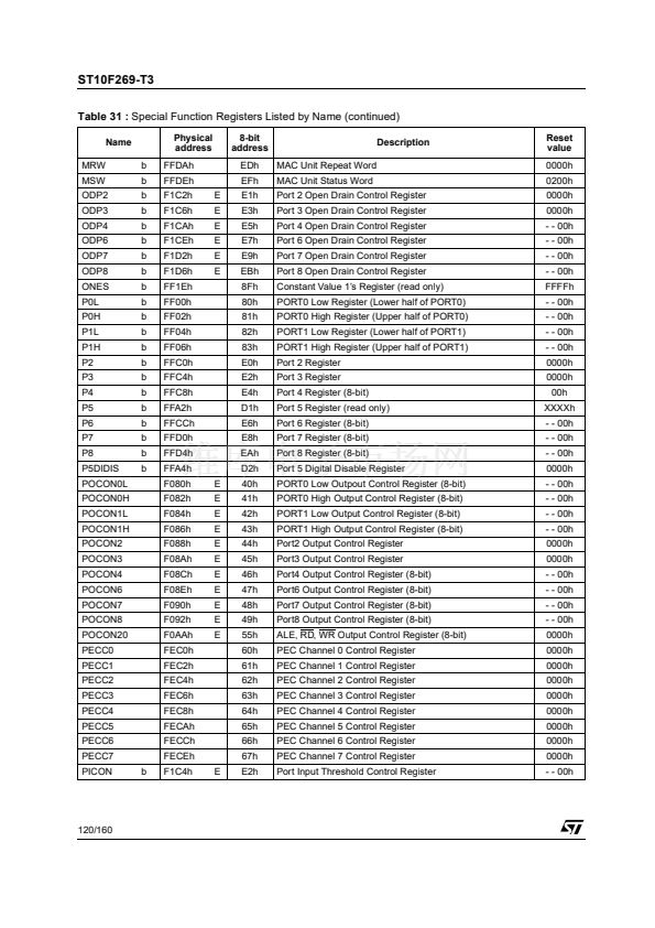
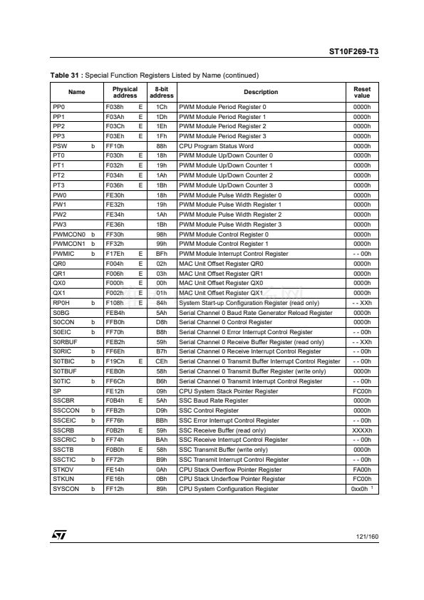
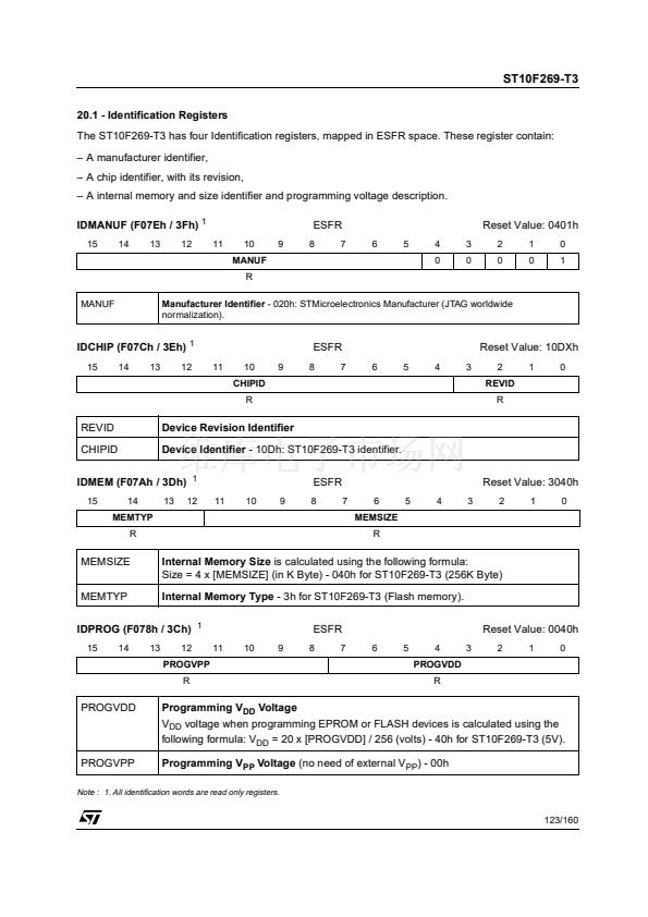
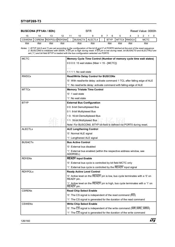
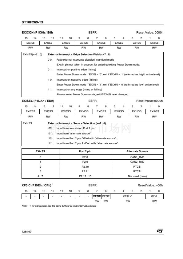
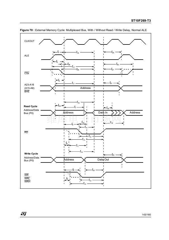
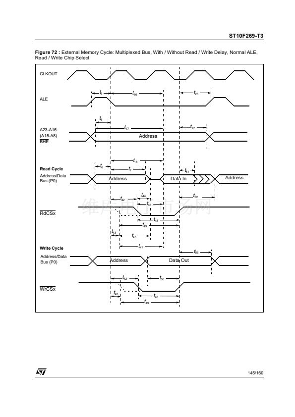
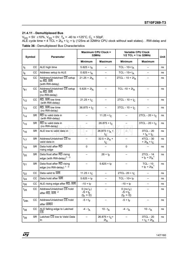
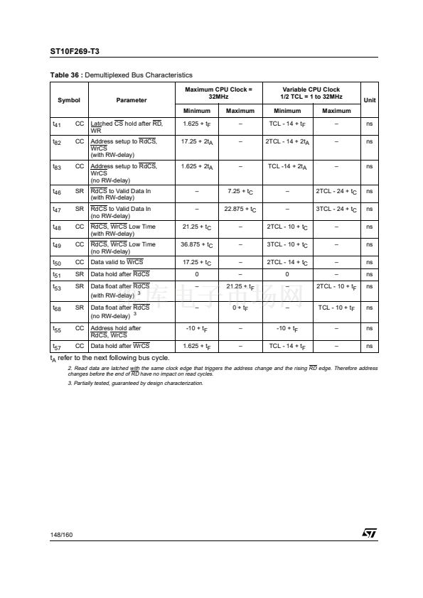
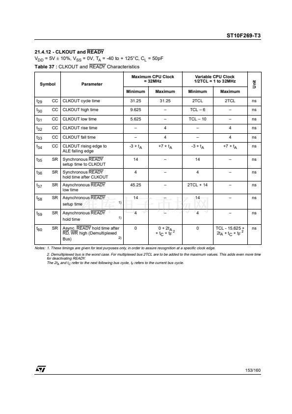
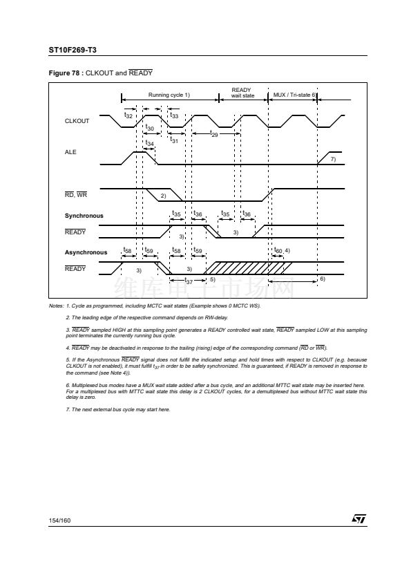
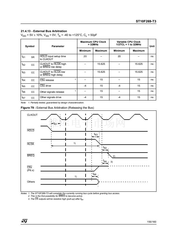
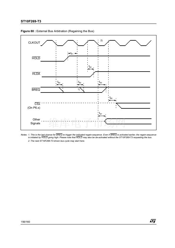
ST10F269-T3
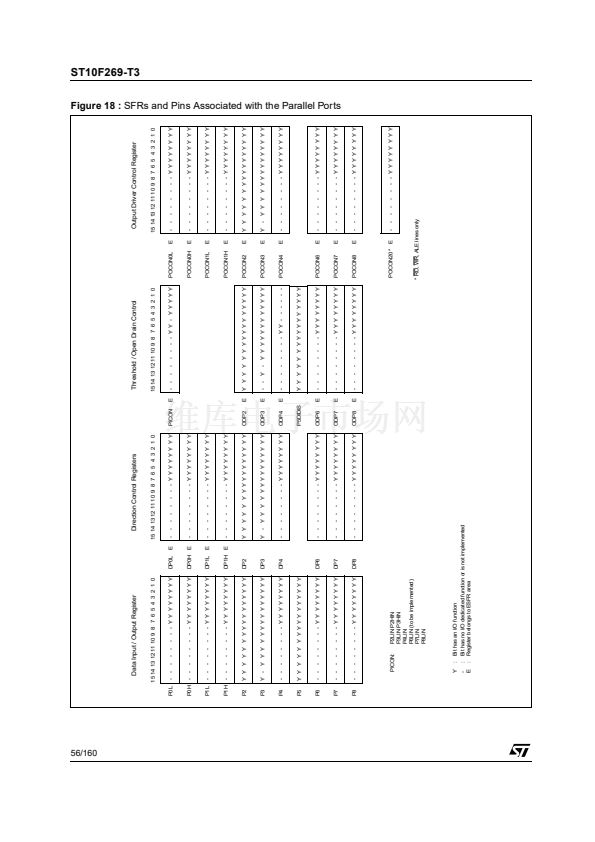
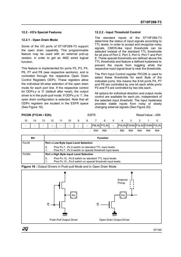
12.2 - I/O鈥檚 Special Features
12.2.1 - Open Drain Mode
Some of the I/O ports of ST10F269-T3 support
the open drain capability. This programmable
feature may be used with an external pull-up
resistor, in order to get an AND wired logical
function.
This feature is implemented for ports P2, P3, P4,
P6, P7 and P8 (see respective sections), and is
controlled through the respective Open Drain
Control Registers ODPx. These registers allow
the individual bit-wise selection of the open drain
mode for each port line. If the respective control
bit ODPx.y is 鈥?鈥?(default after reset), the output
driver is in the push-pull mode. If ODPx.y is 鈥?鈥? the
open drain configuration is selected. Note that all
ODPx registers are located in the ESFR space
(See Figure 19).
PICON (F1C4h / E2h)
15
-
14
-
13
-
12
-
11
-
10
-
9
-
12.2.2 - Input Threshold Control
The standard inputs of the ST10F269-T3
determine the status of input signals according to
TTL levels. In order to accept and recognize noisy
signals, CMOS-like input thresholds can be
selected instead of the standard TTL thresholds
for all pins of Port 2, Port 3, Port 4, Port 7 and Port
8. These special thresholds are defined above the
TTL thresholds and feature a defined hysteresis to
prevent the inputs from toggling while the
respective input signal level is near the thresholds.
The Port Input Control register PICON is used to
select these thresholds for each Byte of the
indicated ports, this means the 8-bit ports P4, P7
and P8 are controlled by one bit each while ports
P2 and P3 are controlled by two bits each.
All options for individual direction and output mode
control are available for each pin, independent of
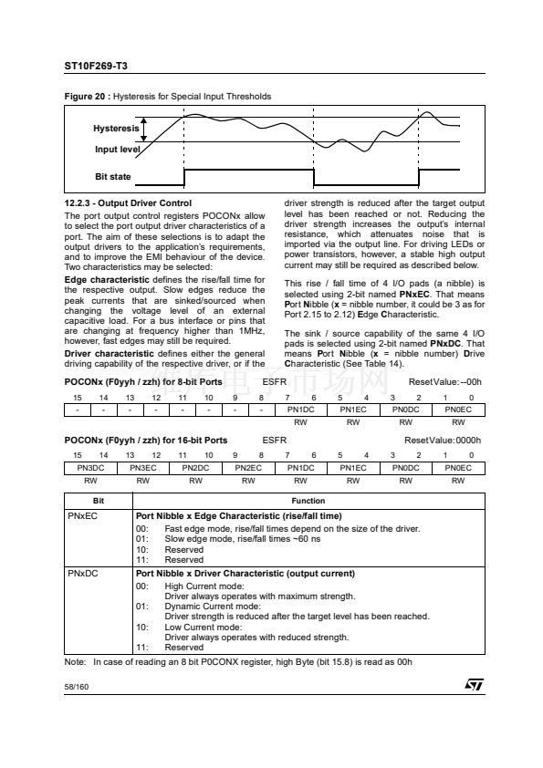
the selected input threshold. The input hysteresis
provides stable inputs from noisy or slowly
changing external signals (See Figure 20).
Reset Value: --00h
6
5
-
4
3
2
1
0
ESFR
8
-
7
P8LIN P7LIN
RW
RW
P4LIN P3HIN P3LIN P2HIN P2LIN
RW
RW
RW
RW
RW
Bit
PxLIN
Port x Low Byte Input Level Selection
0:
1:
PxHIN
0:
1:
Function
Pins Px.7...Px.0 switch on standard TTL input levels
Pins Px.7...Px.0 switch on special threshold input levels
Pins Px.15...Px.8 switch on standard TTL input levels
Pins Px.15...Px.8 switch on special threshold input levels
Port x High Byte Input Level Selection
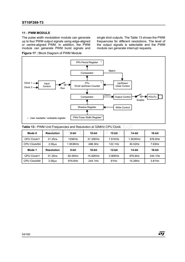
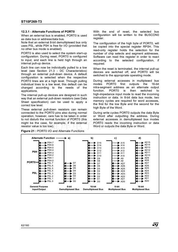
Figure 19 :
Output Drivers in Push-pull Mode and in Open Drain Mode
External
Pullup
Pin
Pin
Q
Q
Push-Pull Output Driver
Open Drain Output Driver
57/160


 1
1
 2
2
 3
3
 4
4
 5
5
 6
6
 7
7
 8
8
 9
9
 10
10
 11
11
 12
12
 13
13
 14
14
 15
15
 16
16
 17
17
 18
18
 19
19
 20
20
 21
21
 22
22
 23
23
 24
24
 25
25
 26
26
 27
27
 28
28
 29
29
 30
30
 31
31
 32
32
 33
33
 34
34
 35
35
 36
36
 37
37
 38
38
 39
39
 40
40
 41
41
 42
42
 43
43
 44
44
 45
45
 46
46
 47
47
 48
48
 49
49
 50
50
 51
51
 52
52
 53
53
 54
54
 55
55
 56
56
 57
57
 58
58
 59
59
 60
60
 61
61
 62
62
 63
63
 64
64
 65
65
 66
66
 67
67
 68
68
 69
69
 70
70
 71
71
 72
72
 73
73
 74
74
 75
75
 76
76
 77
77
 78
78
 79
79
 80
80
 81
81
 82
82
 83
83
 84
84
 85
85
 86
86
 87
87
 88
88
 89
89
 90
90
 91
91
 92
92
 93
93
 94
94
 95
95
 96
96
 97
97
 98
98
 99
99
 100
100
 101
101
 102
102
 103
103
 104
104
 105
105
 106
106
 107
107
 108
108
 109
109
 110
110
 111
111
 112
112
 113
113
 114
114
 115
115
 116
116
 117
117
 118
118
 119
119
 120
120
 121
121
 122
122
 123
123
 124
124
 125
125
 126
126
 127
127
 128
128
 129
129
 130
130
 131
131
 132
132
 133
133
 134
134
 135
135
 136
136
 137
137
 138
138
 139
139
 140
140
 141
141
 142
142
 143
143
 144
144
 145
145
 146
146
 147
147
 148
148
 149
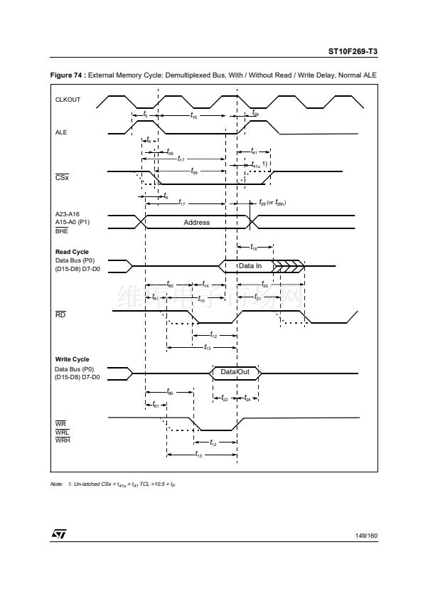
149
 150
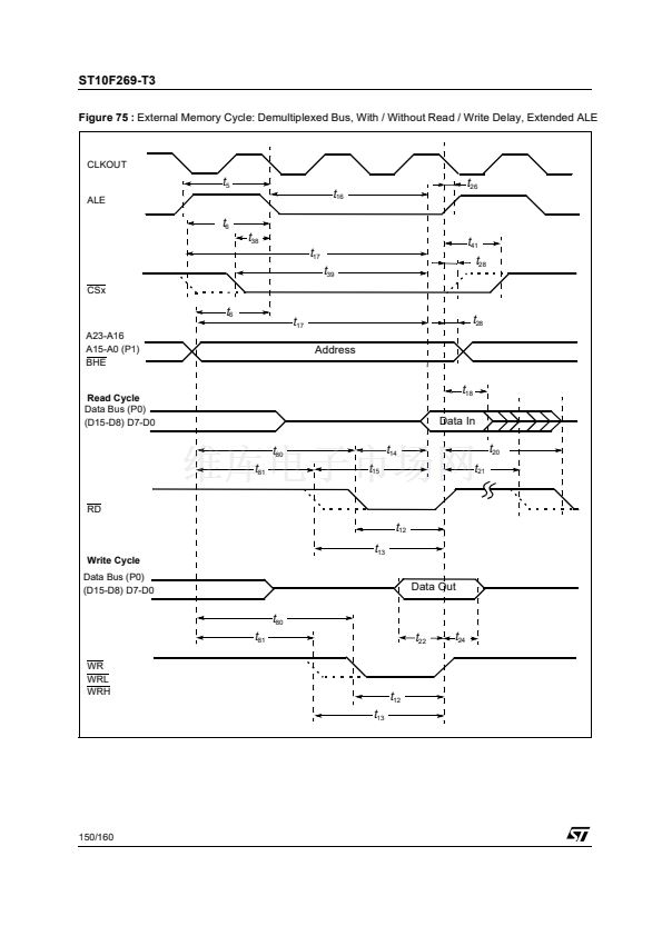
150
 151
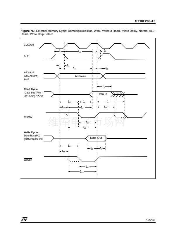
151
 152
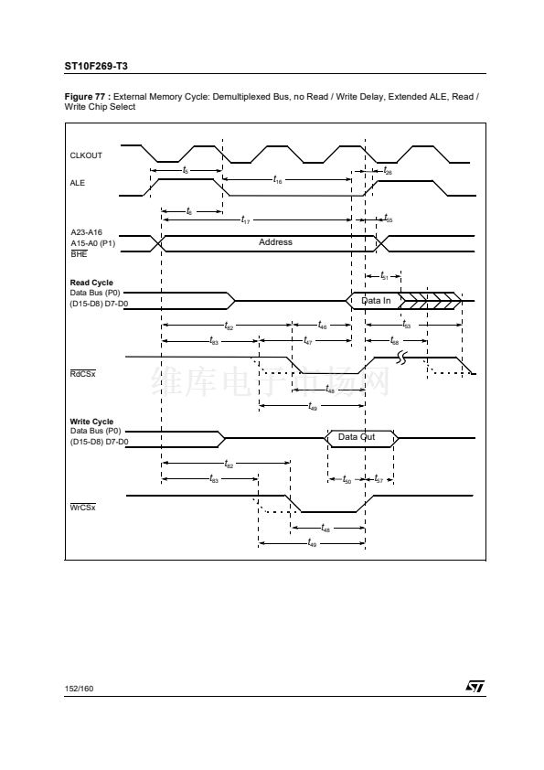
152
 153
153
 154
154
 155
155
 156
156
 157
157
 158
158
 159
159
 160
160
