ST10F269-T3
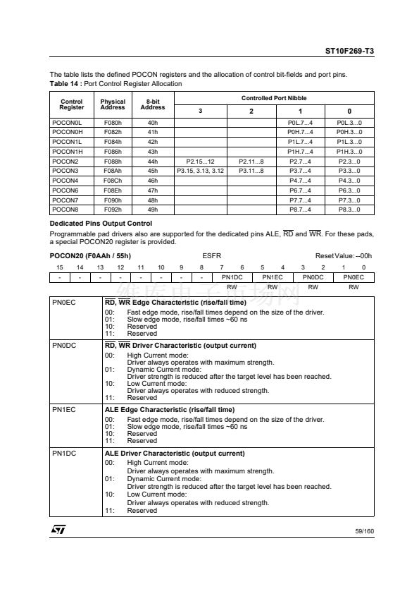
The table lists the defined POCON registers and the allocation of control bit-fields and port pins.
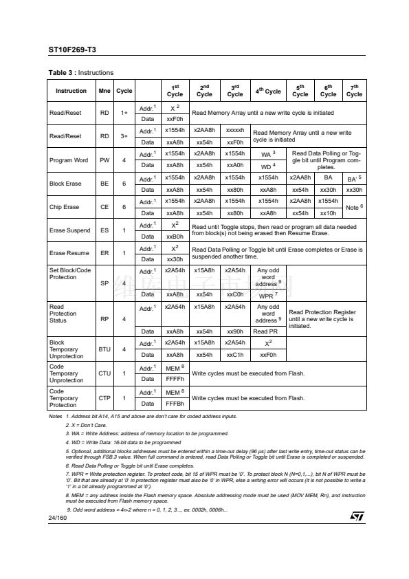
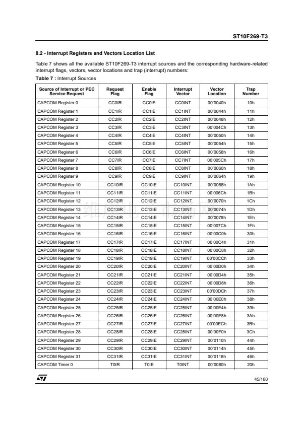
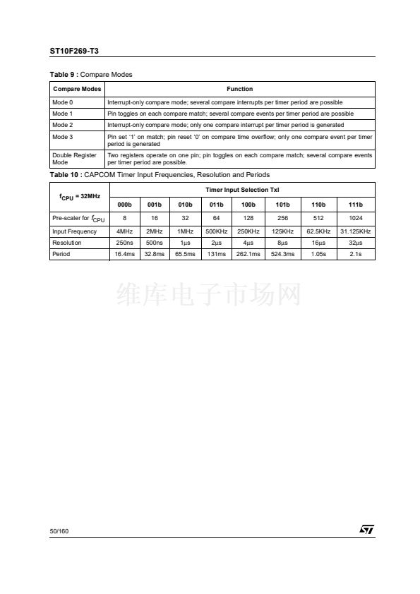
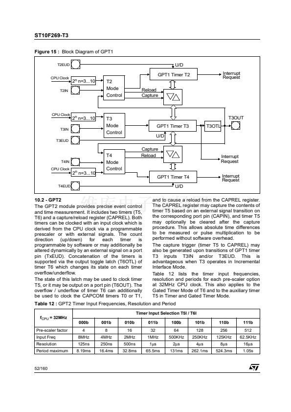
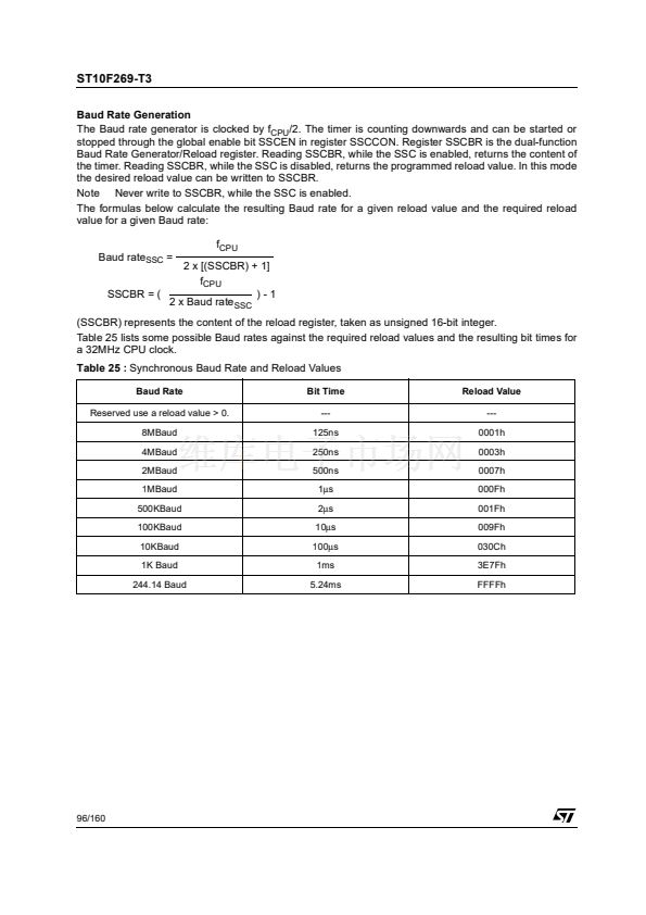
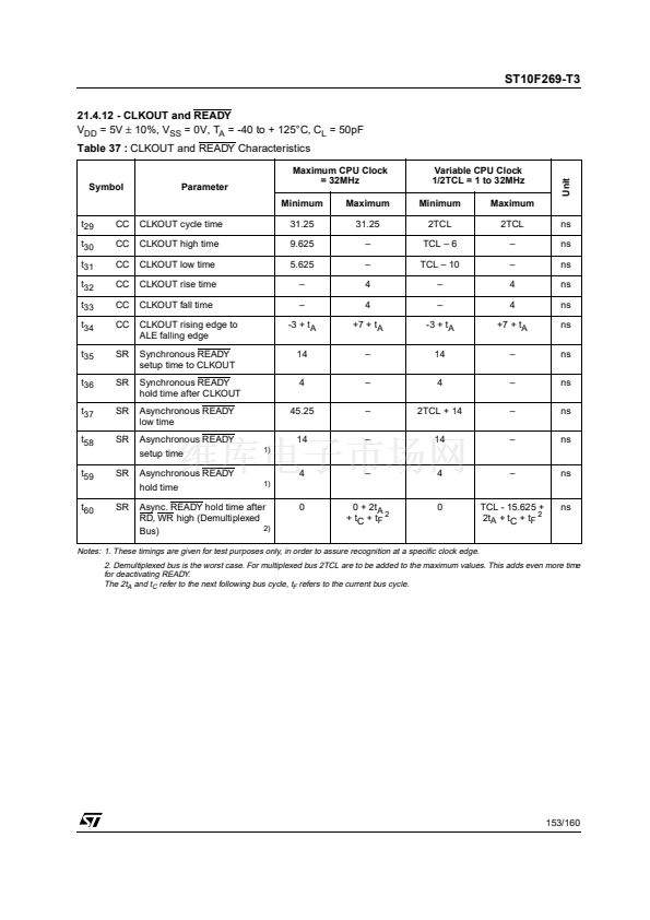
Table 14 :
Port Control Register Allocation
Control
Register
POCON0L
POCON0H
POCON1L
POCON1H
POCON2
POCON3
POCON4
POCON6
POCON7
POCON8
Physical
Address
F080h
F082h
F084h
F086h
F088h
F08Ah
F08Ch
F08Eh
F090h
F092h
8-bit
Address
40h
41h
42h
43h
44h
45h
46h
47h
48h
49h
P2.15...12
P3.15, 3.13, 3.12
P2.11...8
P3.11...8
Controlled Port Nibble
3
2
1
P0L.7...4
P0H.7...4
P1L.7...4
P1H.7...4
P2.7...4
P3.7...4
P4.7...4
P6.7...4
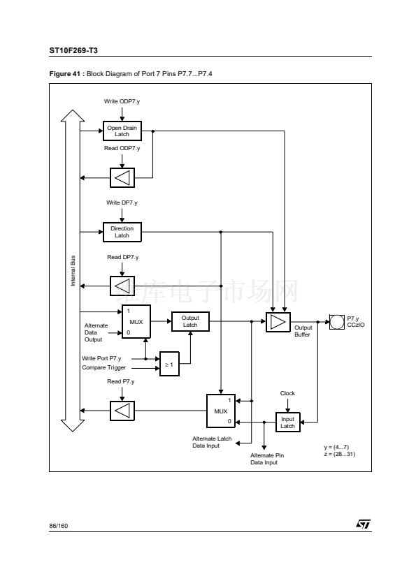
P7.7...4
P8.7...4
0
P0L.3...0
P0H.3...0
P1L.3...0
P1H.3...0
P2.3...0
P3.3...0
P4.3...0
P6.3...0
P7.3...0
P8.3...0
Dedicated Pins Output Control
Programmable pad drivers also are supported for the dedicated pins ALE, RD and WR. For these pads,
a special POCON20 register is provided.
POCON20 (F0AAh / 55h)
15
-
14
-
13
-
12
-
11
-
10
-
9
-
ESFR
8
-
7
RW
6
5
RW
4
3
PN1DC
PN1EC
Reset Value: --00h
2
RW
1
RW
0
PN0DC
PN0EC
PN0EC
RD, WR Edge Characteristic (rise/fall time)
00:
Fast edge mode, rise/fall times depend on the size of the driver.
01:
Slow edge mode, rise/fall times ~60 ns
10:
Reserved
11:
Reserved
RD, WR Driver Characteristic (output current)
00:
High Current mode:
Driver always operates with maximum strength.
01:
Dynamic Current mode:
Driver strength is reduced after the target level has been reached.
10:
Low Current mode:
Driver always operates with reduced strength.
11:
Reserved
ALE Edge Characteristic (rise/fall time)
00:
Fast edge mode, rise/fall times depend on the size of the driver.
01:
Slow edge mode, rise/fall times ~60 ns
10:
Reserved
11:
Reserved
ALE Driver Characteristic (output current)
00:
High Current mode:
Driver always operates with maximum strength.
01:
Dynamic Current mode:
Driver strength is reduced after the target level has been reached.
10:
Low Current mode:
Driver always operates with reduced strength.
11:
Reserved
59/160
PN0DC
PN1EC
PN1DC


 1
1
 2
2
 3
3
 4
4
 5
5
 6
6
 7
7
 8
8
 9
9
 10
10
 11
11
 12
12
 13
13
 14
14
 15
15
 16
16
 17
17
 18
18
 19
19
 20
20
 21
21
 22
22
 23
23
 24
24
 25
25
 26
26
 27
27
 28
28
 29
29
 30
30
 31
31
 32
32
 33
33
 34
34
 35
35
 36
36
 37
37
 38
38
 39
39
 40
40
 41
41
 42
42
 43
43
 44
44
 45
45
 46
46
 47
47
 48
48
 49
49
 50
50
 51
51
 52
52
 53
53
 54
54
 55
55
 56
56
 57
57
 58
58
 59
59
 60
60
 61
61
 62
62
 63
63
 64
64
 65
65
 66
66
 67
67
 68
68
 69
69
 70
70
 71
71
 72
72
 73
73
 74
74
 75
75
 76
76
 77
77
 78
78
 79
79
 80
80
 81
81
 82
82
 83
83
 84
84
 85
85
 86
86
 87
87
 88
88
 89
89
 90
90
 91
91
 92
92
 93
93
 94
94
 95
95
 96
96
 97
97
 98
98
 99
99
 100
100
 101
101
 102
102
 103
103
 104
104
 105
105
 106
106
 107
107
 108
108
 109
109
 110
110
 111
111
 112
112
 113
113
 114
114
 115
115
 116
116
 117
117
 118
118
 119
119
 120
120
 121
121
 122
122
 123
123
 124
124
 125
125
 126
126
 127
127
 128
128
 129
129
 130
130
 131
131
 132
132
 133
133
 134
134
 135
135
 136
136
 137
137
 138
138
 139
139
 140
140
 141
141
 142
142
 143
143
 144
144
 145
145
 146
146
 147
147
 148
148
 149
149
 150
150
 151
151
 152
152
 153
153
 154
154
 155
155
 156
156
 157
157
 158
158
 159
159
 160
160
